Page 1212 of 4264

6A – 72 ENGINE MECHANICAL
012RY00022
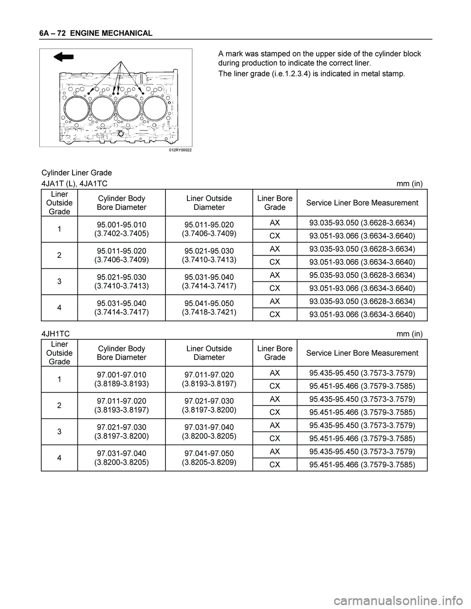
A mark was stamped on the upper side of the cylinder block
during production to indicate the correct liner.
The liner grade (i.e.1.2.3.4) is indicated in metal stamp.
Cylinder Liner Grade
4JA1T (L), 4JA1TC mm (in)
Liner
Outside
Grade Cylinder Body
Bore Diameter Liner Outside
Diameter Liner Bore
Grade Service Liner Bore Measurement
AX 93.035-93.050 (3.6628-3.6634) 1 95.001-95.010
(3.7402-3.7405) 95.011-95.020
(3.7406-3.7409)
CX 93.051-93.066 (3.6634-3.6640)
AX 93.035-93.050 (3.6628-3.6634) 2 95.011-95.020
(3.7406-3.7409) 95.021-95.030
(3.7410-3.7413)
CX 93.051-93.066 (3.6634-3.6640)
AX 95.035-93.050 (3.6628-3.6634) 3 95.021-95.030
(3.7410-3.7413) 95.031-95.040
(3.7414-3.7417)
CX 93.051-93.066 (3.6634-3.6640)
AX 93.035-93.050 (3.6628-3.6634) 4 95.031-95.040
(3.7414-3.7417) 95.041-95.050
(3.7418-3.7421)
CX 93.051-93.066 (3.6634-3.6640)
4JH1TC mm (in)
Liner
Outside
Grade Cylinder Body
Bore Diameter Liner Outside
Diameter Liner Bore
Grade Service Liner Bore Measurement
AX 95.435-95.450 (3.7573-3.7579) 1 97.001-97.010
(3.8189-3.8193) 97.011-97.020
(3.8193-3.8197)
CX 95.451-95.466 (3.7579-3.7585)
AX 95.435-95.450 (3.7573-3.7579) 2 97.011-97.020
(3.8193-3.8197) 97.021-97.030
(3.8197-3.8200)
CX 95.451-95.466 (3.7579-3.7585)
AX 95.435-95.450 (3.7573-3.7579) 3 97.021-97.030
(3.8197-3.8200) 97.031-97.040
(3.8200-3.8205)
CX 95.451-95.466 (3.7579-3.7585)
AX 95.435-95.450 (3.7573-3.7579) 4 97.031-97.040
(3.8200-3.8205) 97.041-97.050
(3.8205-3.8209)
CX 95.451-95.466 (3.7579-3.7585)
Page 1217 of 4264

ENGINE MECHANICAL 6A – 77
CAMSHAFT
Visually inspect the journals, the cams, the oil pump drive gear,
and the camshaft bearings for excessive wear and damage.
The camshaft and the camshaft bearings must be replaced if
these conditions are discovered during inspection.
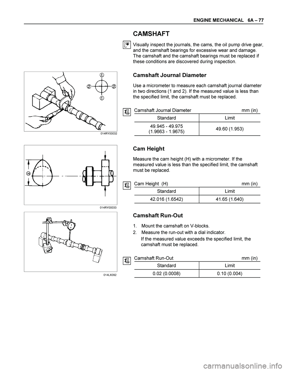
Camshaft Journal Diameter
Use a micrometer to measure each camshaft journal diameter
in two directions (1 and 2). If the measured value is less than
the specified limit, the camshaft must be replaced.
Camshaft Journal Diameter mm (in)
Standard Limit
49.945 - 49.975
(1.9663 - 1.9675) 49.60 (1.953)
Cam Height
Measure the cam height (H) with a micrometer. If the
measured value is less than the specified limit, the camshaft
must be replaced.
Cam Height (H) mm (in)
Standard Limit
42.016 (1.6542) 41.65 (1.640)
Camshaft Run-Out
1. Mount the camshaft on V-blocks.
2. Measure the run-out with a dial indicator.
If the measured value exceeds the specified limit, the
camshaft must be replaced.
Camshaft Run-Out mm (in)
Standard Limit
0.02 (0.0008) 0.10 (0.004)
014RY00032
014RY00033
014LX092
Page 1250 of 4264

6A – 110 ENGINE MECHANICAL
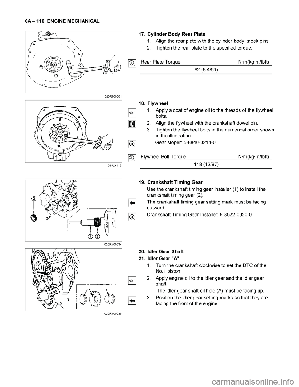
17. Cylinder Body Rear Plate
1. Align the rear plate with the cylinder body knock pins.
2. Tighten the rear plate to the specified torque.
Rear Plate Torque N·m(kg·m/lbft)
82 (8.4/61)
18. Flywheel
1. Apply a coat of engine oil to the threads of the flywheel
bolts.
2. Align the flywheel with the crankshaft dowel pin.
3. Tighten the flywheel bolts in the numerical order shown
in the illustration.
Gear stoper: 5-8840-0214-0
Flywheel Bolt Torque N·m(kg·m/lbft)
118 (12/87)
19. Crankshaft Timing Gear
Use the crankshaft timing gear installer (1) to install the
crankshaft timing gear (2).
The crankshaft timing gear setting mark must be facing
outward.
Crankshaft Timing Gear Installer: 9-8522-0020-0
20. Idler Gear Shaft
21. Idler Gear "A"
1. Turn the crankshaft clockwise to set the DTC of the
No.1 piston.
2. Apply engine oil to the idler gear and the idler gear
shaft.
The idler gear shaft oil hole (A) must be facing up.
3. Position the idler gear setting marks so that they are
facing the front of the engine.
015LX113 020R100001
020RY00034
020RY00035
Page 1251 of 4264

ENGINE MECHANICAL 6A – 111
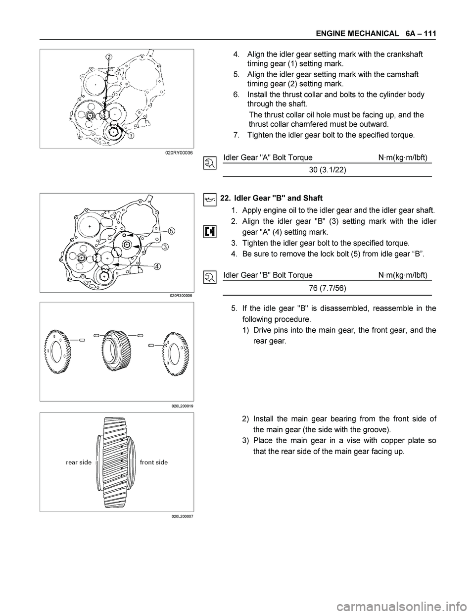
4. Align the idler gear setting mark with the crankshaft
timing gear (1) setting mark.
5. Align the idler gear setting mark with the camshaft
timing gear (2) setting mark.
6. Install the thrust collar and bolts to the cylinder body
through the shaft.
The thrust collar oil hole must be facing up, and the
thrust collar chamfered must be outward.
7. Tighten the idler gear bolt to the specified torque.
Idler Gear "A" Bolt Torque N·m(kg·m/lbft)
30 (3.1/22)
020R300006
22. Idler Gear "B" and Shaft
1. Apply engine oil to the idler gear and the idler gear shaft.
2.
Align the idler gear "B" (3) setting mark with the idler
gear "A" (4) setting mark.
3. Tighten the idler gear bolt to the specified torque.
4. Be sure to remove the lock bolt (5) from idle gear “B”.
Idler Gear "B" Bolt Torque N·m(kg·m/lbft)
76 (7.7/56)
020L200019
5. If the idle gear "B" is disassembled, reassemble in the
following procedure.
1) Drive pins into the main gear, the front gear, and the
rear gear.
020L200007
2) Install the main gear bearing from the front side of
the main gear (the side with the groove).
3) Place the main gear in a vise with copper plate so
that the rear side of the main gear facing up.
020RY00036
Page 1253 of 4264
ENGINE MECHANICAL 6A – 113
RTW31BSH000401
8) Insert the bolts of the special tool into the rear gear
setting hole. Rotate the rear gear to mesh the teeth
of main gear and rear gear.
9) Insert a lock bolt (M6 � 1 L=30) into scissors gea
r
fixing hole to prevent the scissors gear from turning.
10) Place the main gear in a vise with copper plate so
that the front side of the main gear facing up.
11) Repeat steps 4 to 8 to install the front gear.
12) Lock the front gear, the main gear, and the rear gea
r
with lock bolt (inserted at Step 8).
Page 1259 of 4264
ENGINE MECHANICAL 6A – 119
Installation
1. Exhaust Manifold
1) Install the exhaust manifold to the cylinder head with
the manifold gasket.
2) Tighten the exhaust manifold bolts and nuts to the
specified torque a little at a time.
Exhaust Manifold Bolt and Nuts
Torque N·m(kg·m/Ib ft)
27 (2.7/20)
3) Install the exhaust manifold bracket to the manifold
and the cylinder body.
Manifold Bracket Bolt Torque N·m(kg·m/Ib ft)
19 (1.9/14)
RTW46ASH001301
2. Oil Cooler with Oil Filter
1) Install the O-ring to the oil filter body flange groove.
2) Install the oil filter body to cylinder block and tighten to
the specified torque.
Oil Filter Body Bolt and Nut
Torque N·m(kg·m/Ib ft)
BOLT 19 (1.9/14)
NUT 24 (2.4/17)
3. Generator Bracket
Install the generator bracket to the cylinder body and
tighten the bracket bolts to the specified torque.
Bracket Bolt Torque N·m(kg·m/Ib ft)
40 (4.1/30)
027R100003
027R100004
066RY00001
Page 1296 of 4264
6B – 16 ENGINE COOLING
P1010064
Removal
1. Disconnect battery ground cable.
2. Loosen a drain plug to drain EC.
3. Disconnect oil cooler hose on automatic transmission (A/T).
4. Disconnect radiator inlet hose and outlet hose from the engine.
PTW46BSH000101
5. Remove fan guide(1), clips(2) on both sides and the bottom
lock, then remove lower fan guide(3) with fan shroud(4).
6. Disconnect the reserve tank hose(6) from radiator.
RTW36BMH000101
7. Remove bracket(5).
8. Lift up and remove the radiator assembly with hose, taking
care not to damage the radiator core with a fan blade.
Page 1312 of 4264
6C – 12 FUEL SYSTEM
FUEL GAUGE UNIT
Fuel Gauge Unit and Associated Parts
RTW46CLF000501
Legend
1. Fuel Feed Port
2. Fuel Return Port
3. Fuel Emission Port
4. Fuel Gauge Unit and Sender Assembly
5. Connector; Fuel Gauge Unit
6. Fuel Tube/Quick Connector
7. Retainer Ring (Fuel Gauge Unit Lock)
8. Seal; Fuel Gauge Unit
9. Fuel Tank Assembly
10. Evapo Tube/Quick Connector