Page 1065 of 4264
ELECTRICAL-BODY AND CHASSIS 8A-407
CIRCUIT DIAGRAM ANTI THEFT WITH SUPER LOCK (RHD) Sheet 3/3
RTW48AXF024901
Page 1068 of 4264
8A-410 ELECTRICAL-BODY AND CHASSIS
ANTI THEFT INDICATOR
Removal
1. Disconnect the battery ground cable.
RTW3A0SH001301
2. Remove the side ventilation grille.
RTW08ASH000101
3. Disconnect the indicator connector and screw from the
backside of the side ventilation grille to remove the anti thef
t
indicator.
Installation
To install, follow the removal steps in the reverse order, noting
the following point.
1. Push in the switch with your fingers until it locks securely.
Page 1076 of 4264
8A-418 ELECTRICAL-BODY AND CHASSIS
CONNECTOR LIST
No. Connector face No. Connector face
B-1
~
B-6 NOT USED B-17
~
B-19 NOT USED
B-7
Black
Rear defogger relay B-20
WhiteCigar lighter illumination
B-8
Black
Power Window Relay B-21
WhiteCigar lighter
B-9
NOT USED B-22
Black
Cigar lighter
B-10
White
Clock B-23
GreenMeter-A
B-11
�
B-12 NOT USED B-24
Green
Meter-B
B-13
White
Fan switch B-25
~
B-27 NOT USED
B-14
Gray
Audio B-24
GreenGround Driver Side
B-15
NOT USED B-30
~
B-29 NOT USED
B-16
White
Hazard switch B-31
SDM
Page 1078 of 4264
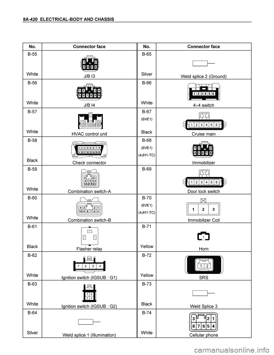
8A-420 ELECTRICAL-BODY AND CHASSIS
No. Connector face No. Connector face
B-55
White
J/B I3 B-65
SilverWeld splice 2 (Ground)
B-56
White
J/B I4 B-66
White4�4 switch
B-57
White
HVAC control unit B-67
(6VE1)
BlackCruise main
B-58
Black
Check connector B-68
(6VE1)
(4JH1-TC)
Immobilizer
B-59
White
Combination switch-A B-69
Door lock switch
B-60
White
Combination switch-B B-70
(6VE1)
(4JH1-TC)
Immobilizer Coil
B-61
Black
Flasher relay B-71
YellowHorn
B-62
White
Ignition switch (IGSUB : G1) B-72
YellowSRS
B-63
White
Ignition switch (IGSUB : G2) B-73
BlackWeld Splice 3
B-64
Silver
Weld splice 1 (Illumination) B-74
WhiteCellular phone
Page 1084 of 4264
8A-426 ELECTRICAL-BODY AND CHASSIS
No. Connector face No. Connector face
D-1
Brown
Power window motor-RH D-10
WhitePower window switch passenger side
D-2
White
Remote mirror-RH D-11
BrownPower window motor Rear-LH
D-3
Black
Front speaker-RH D-12
WhitePower window switch Rear-LH
D-4
Black
Door lock actuator driver side D-13
BlackRear speaker-LH
D-5
White
Power window driver side D-14
BlackDoor lock actuator Rear-LH
D-6
Brown
Power window motor-LH D-15
BrownPower window motor Rear-RH
D-7
White
Remote mirror-LH D-16
WhitePower window switch-RH
D-8
Black
Speaker-LH D-17
BlackRear speaker-RH
D-9
Black
Door lock actuator passenger side
(keyless & antitheft) D-18
BlackDoor lock actuator Rear-RH
D-9
Black
Door lock actuator passenger side D-19
WhiteRemote mirror switch driver side
Page 1085 of 4264
ELECTRICAL-BODY AND CHASSIS 8A-427
No. Connector face No. Connector face
D-20
White
Power window switch driver side
D-21
White
Tweeter-RH
D-22
White
Tweeter-LH
D-23
White
Door lock & super actuator front (RH)
D-24
White
Key cylinder switch front –(RH)
D-25
White
Door lock & super lock actuator front (LH)
D-26
White
Key cylinder switch front – (LH)
D-27
White
Door lock & super lock actuator RR (RH)
D-28
White
Door lock & super lock actuator RR (LH)
Page 1101 of 4264
. REFER TO THE SRS
COMPONENT AND WIRING LOCATION VIEW IN ORDER TO DETERMINE WHETHER YOU")
CRUISE CONTROL SYSTEM 8B-3
Service Precaution
WARNING: THIS VEHICLE HAS A SUPPLEMENTAL RESTRAIN SYSTEM (SRS). REFER TO THE SRS
COMPONENT AND WIRING LOCATION VIEW IN ORDER TO DETERMINE WHETHER YOU ARE
PERFORMING SERVICE ON OR NEAR THE SRS COMPONENTS OR THE SRS WIRING. WHEN YOU ARE
PERFORMING SERVICE ON OR NEAR THE SRS COMPONENTS OR THE SRS WIRING, REFER TO THE SRS
SERVICE INFORMATION. FAILURE TO FOLLOW WARNINGS COULD RESULT IN POSSIBLE AIR BAG
DEPLOYMENT, PERSONAL INJURY, OR OTHER WISE UNNEEDED SRS SYSTEM REPAIRS.
CAUTION: Always use the correct fastener in the proper location. When you replace a faster, use ONLY the
exact part number for that application. Dealer will call out those fasteners that require a replacement after
removal. Dealer will also call out the fasteners that require thread lockers or thread sealant. UNLESS
OTHERWISE SPECIFIED, do not use supplemental coatings (Paints, greases, or other corrosion inhibitors)
on threaded fasteners or fastener joint interfaces. Generally, such coatings adversely affect the fastener
torque and joint Clamping force, and may damaged the fastener. When you install fasteners, use the
correct tightening sequence and specifications. Following these instructions can help you avoid damage to
parts and systems.
General Description
The cruise control keeps the vehicle running at a fixed speed until a signal canceling this fixed speed is received.
When the main switch “AUTO CRUISE” is turned on with the vehicle in the running mode, the battery voltage is
applied to the control unit. When a signal from the control unit while the vehicle is in this state, the cruise control
actuator is activated to operate the system. Also, while the system is operating, the “AUTO CRUISE” indicator light
in the meter assembly lights up.
LTW48BSH000101
1. SET/COAST Switch Function
1. Set Function: When the SET/COAST switch is pressed and released with the main switch on, the speed at
which the vehicle is running at that moment is stored in the memory, and the vehicle automatically runs at the
stored speed.
2. COAST-down Function: When the SET/COAST switch is kept on while the vehicle in running, the vehicle
decelerates during that time. The speed at which vehicle is running when the control switch is pressed in the
memory, and the vehicle automatically returns to the stored speed.
3. Tap-down Function: When the SET/COAST switch is pressed and released instantaneously while the
vehicle is running, the vehicle decelerates a mile for each on/off operation. The vehicle speed at which the
vehicle was running when the SET/COAST was released last is stored in the memory, and the vehicle
automatically returns to this stored speed.
Page 1103 of 4264
CRUISE CONTROL SYSTEM 8B-5
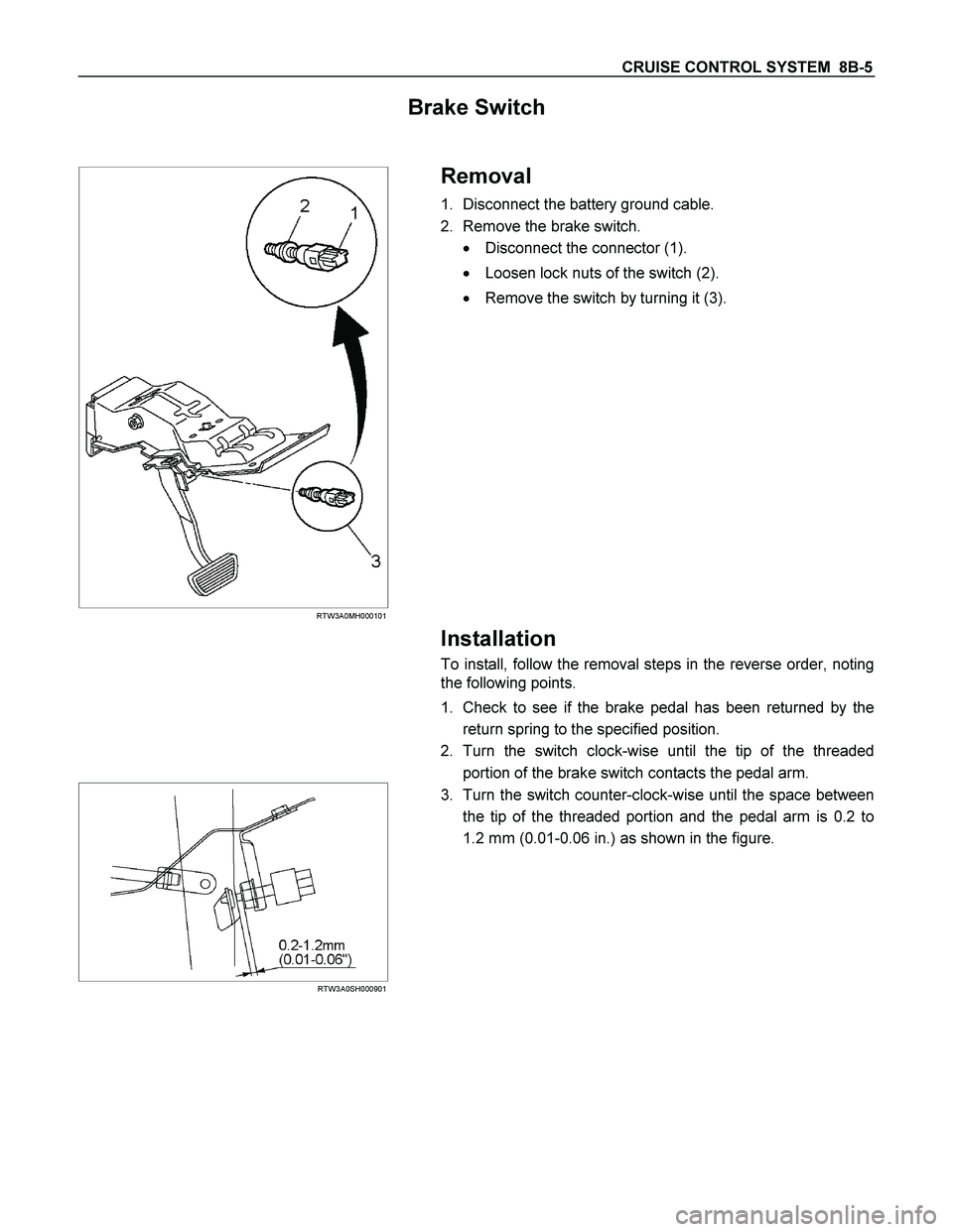
Brake Switch
RTW3A0MH000101
Removal
1. Disconnect the battery ground cable.
2. Remove the brake switch.
� Disconnect the connector (1).
� Loosen lock nuts of the switch (2).
� Remove the switch by turning it (3).
Installation
To install, follow the removal steps in the reverse order, noting
the following points.
1. Check to see if the brake pedal has been returned by the
return spring to the specified position.
2. Turn the switch clock-wise until the tip of the threaded
portion of the brake switch contacts the pedal arm.
RTW3A0SH000901
3. Turn the switch counter-clock-wise until the space between
the tip of the threaded portion and the pedal arm is 0.2 to
1.2 mm (0.01-0.06 in.) as shown in the figure.
 Sheet 3/3
RTW48AXF024901")