Page 1104 of 4264
8B-6 CRUISE CONTROL SYSTEM
Adjustment
1. Check to be sure that the brake pedal has been completely
returned by the return spring.
2. Disconnect the switch connector.
RTW3A0SH001201
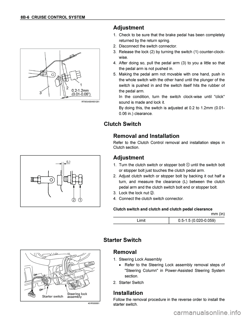
3. Release the lock (2) by turning the switch (1) counter-clock-
wise.
4. After doing so, pull the pedal arm (3) to you a little so tha
t
the pedal arm is not pushed in.
5. Making the pedal arm not movable with one hand, push in
the whole switch with the other hand until the plunger of the
switch is pushed in and the switch itself hits the rubber o
f
the pedal arm.
In the condition, turn the switch clock-wise until "click"
sound is made and lock it.
By doing this, the switch is adjusted at 0.2 to 1.2mm (0.01-
0.06 in.) clearance.
Clutch Switch
Removal and Installation
Refer to the Clutch Control removal and installation steps in
Clutch section.
Adjustment
1. Turn the clutch switch or stopper bolt 1 until the switch bolt
or stopper bolt just touches the clutch pedal arm.
2. Adjust clutch switch or stopper bolt by backing it out half a
turn, and measure the clearance (L) between the clutch
pedal arm and the clutch switch bolt end or stopper bolt.
3. Lock the lock nut
2.
4. Connect the clutch switch connector.
Clutch switch and clutch and clutch pedal clearance
mm (in)
Limit 0.5-1.5 (0.020-0.059)
Starter Switch
431R300001
Removal
1. Steering Lock Assembly
� Refer to the Steering Lock assembly removal steps o
f
"Steering Column" in Power-Assisted Steering System
section.
2. Starter Switch
Installation
Follow the removal procedure in the reverse order to install the
starter switch.
Page 1105 of 4264
CRUISE CONTROL SYSTEM 8B-7
Cruise Control Main Switch
Removal
1. Disconnect the battery ground cable.
RTW3A0SH001301
2. Remove the side ventilation grille.
RTW3A0SH001401
3. Disconnect the switch connector and push the lock from the
backside of the side ventilation grille to remove the cruise
control main switch.
Installation
To install, follow the removal steps in the reverse order, noting
the following point.
1. Push in the switch with your fingers until it locks securely.
Cruise Control Switch (Combination Switch)
Removal and Installation
Refer to the Lighting Switch (Combination Switch) removal and
installation steps of Lighting System in Body and Accessories
section.
Page 1125 of 4264
TROUBLESHOOTING 6 – 5
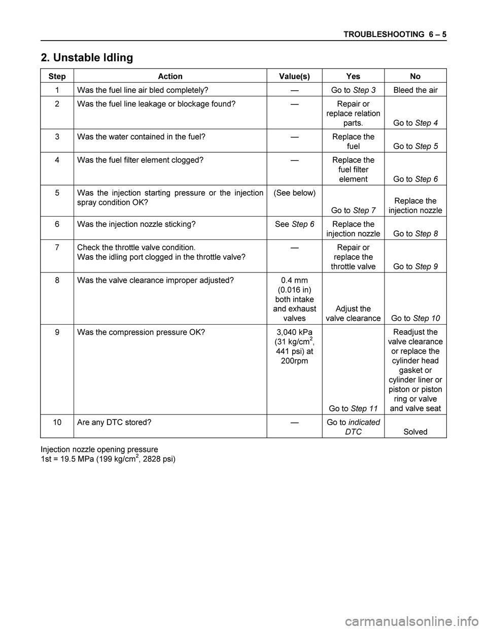
2. Unstable Idling
Step Action Value(s) Yes No
1 Was the fuel line air bled completely? — Go to Step 3 Bleed the air
2 Was the fuel line leakage or blockage found? — Repair or
replace relation
parts. Go to Step 4
3 Was the water contained in the fuel? — Replace the
fuel Go to Step 5
4 Was the fuel filter element clogged? — Replace the
fuel filter
element Go to Step 6
5 Was the injection starting pressure or the injection
spray condition OK? (See below)
Go to Step 7 Replace the
injection nozzle
6 Was the injection nozzle sticking? See Step 6 Replace the
injection nozzle Go to Step 8
7 Check the throttle valve condition.
Was the idling port clogged in the throttle valve? — Repair or
replace the
throttle valve Go to Step 9
8 Was the valve clearance improper adjusted? 0.4 mm
(0.016 in)
both intake
and exhaust
valves Adjust the
valve clearance Go to Step 10
9 Was the compression pressure OK? 3,040 kPa
(31 kg/cm2,
441 psi) at
200rpm
Go to Step 11 Readjust the
valve clearance
or replace the
cylinder head
gasket or
cylinder liner or
piston or piston
ring or valve
and valve seat
10 Are any DTC stored? — Go to indicated
DTC Solved
Injection nozzle opening pressure
1st = 19.5 MPa (199 kg/cm2, 2828 psi)
Page 1164 of 4264
6A – 24 ENGINE MECHANICAL
SERVICING
Servicing refers to general maintenance procedures to be performed by qualified service personnel.
RTW36ASH000401
MODEL IDENTIFICATION
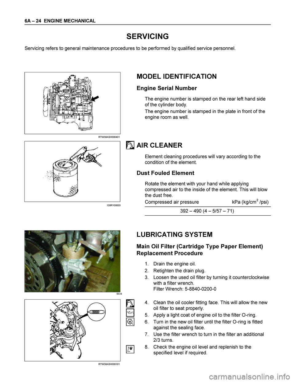
Engine Serial Number
The engine number is stamped on the rear left hand side
of the cylinder body.
The engine number is stamped in the plate in front of the
engine room as well.
AIR CLEANER
Element cleaning procedures will vary according to the
condition of the element.
Dust Fouled Element
Rotate the element with your hand while applying
compressed air to the inside of the element. This will blow
the dust free.
Compressed air pressure kPa (kg/cm
2 /psi)
392 – 490 (4 – 5/57 – 71)
LUBRICATING SYSTEM
Main Oil Filter (Cartridge Type Paper Element)
Replacement Procedure
1. Drain the engine oil.
2. Retighten the drain plug.
3. Loosen the used oil filter by turning it counterclockwise
with a filter wrench.
Filter Wrench: 5-8840-0200-0
RTW36ASH000101
4. Clean the oil cooler fitting face. This will allow the new
oil filter to seat properly.
5. Apply a light coat of engine oil to the filter O-ring.
6. Turn in the new oil filter until the filter O-ring is fitted
against the sealing face.
7. Use the filter wrench to turn in the filter an additional
2/3 turns.
8. Check the engine oil level and replenish to the
specified level if required.
130RY00003
6A-6
Page 1165 of 4264
ENGINE MECHANICAL 6A – 25
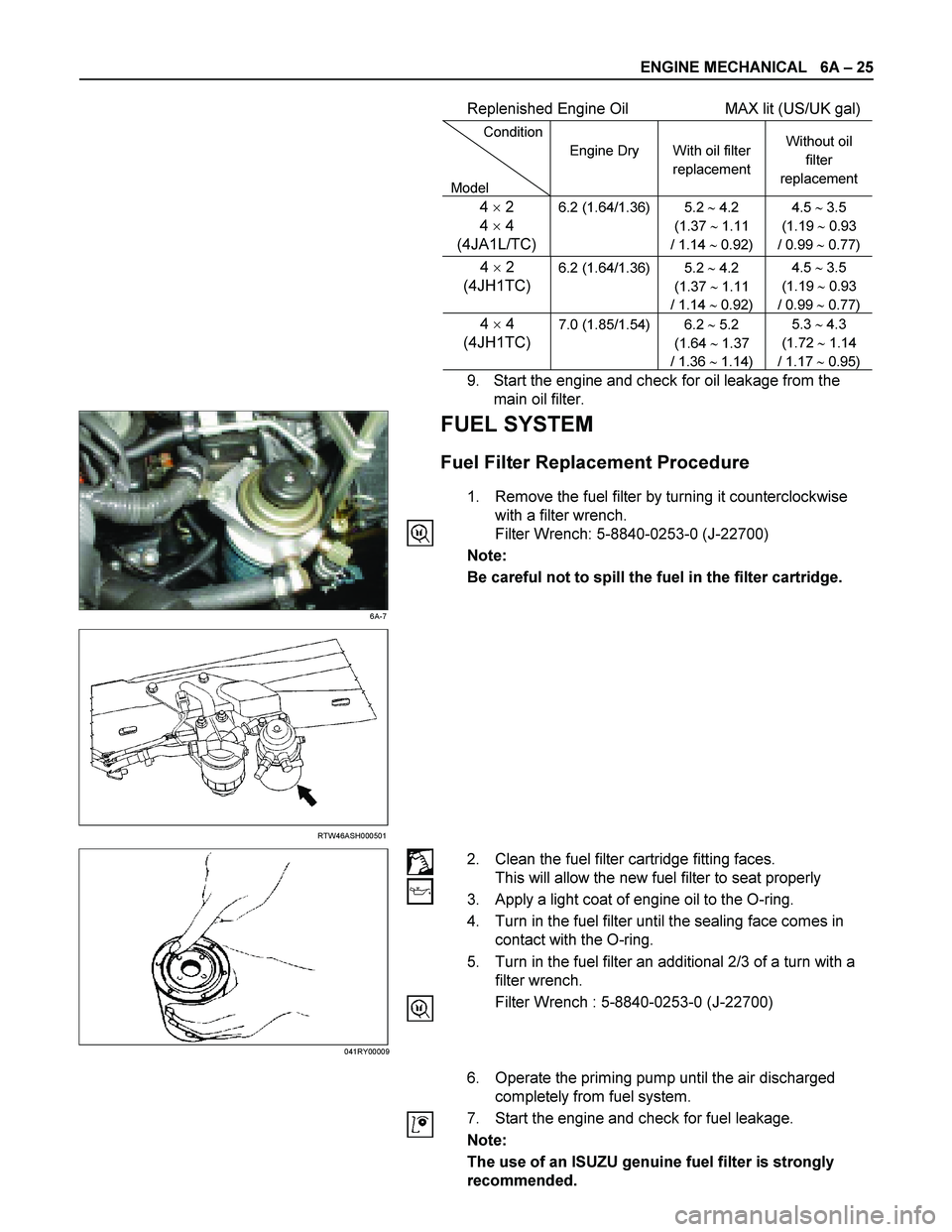
Replenished Engine Oil MAX lit (US/UK gal)
Condition
Model Engine Dry
With oil filter
replacement Without oil
filter
replacement
4 � 2
4 � 4
(4JA1L/TC)6.2 (1.64/1.36) 5.2 � 4.2
(1.37 � 1.11
/ 1.14 � 0.92) 4.5 � 3.5
(1.19 � 0.93
/ 0.99 � 0.77)
4 � 2
(4JH1TC)
6.2 (1.64/1.36) 5.2 � 4.2
(1.37 � 1.11
/ 1.14 � 0.92) 4.5 � 3.5
(1.19 � 0.93
/ 0.99 � 0.77)
4 � 4
(4JH1TC) 7.0 (1.85/1.54) 6.2 � 5.2
(1.64 � 1.37
/ 1.36 � 1.14) 5.3 � 4.3
(1.72 � 1.14
/ 1.17 � 0.95)
9. Start the engine and check for oil leakage from the
main oil filter.
6A-7
FUEL SYSTEM
Fuel Filter Replacement Procedure
1. Remove the fuel filter by turning it counterclockwise
with a filter wrench.
Filter Wrench: 5-8840-0253-0 (J-22700)
Note:
Be careful not to spill the fuel in the filter cartridge.
RTW46ASH000501
2. Clean the fuel filter cartridge fitting faces.
This will allow the new fuel filter to seat properly
3. Apply a light coat of engine oil to the O-ring.
4. Turn in the fuel filter until the sealing face comes in
contact with the O-ring.
5. Turn in the fuel filter an additional 2/3 of a turn with a
filter wrench.
Filter Wrench : 5-8840-0253-0 (J-22700)
6. Operate the priming pump until the air discharged
completely from fuel system.
7. Start the engine and check for fuel leakage.
Note:
The use of an ISUZU genuine fuel filter is strongly
recommended.
041RY00009
Page 1171 of 4264
ENGINE MECHANICAL 6A – 31
VALVE CLEARANCE ADJUSTMENT
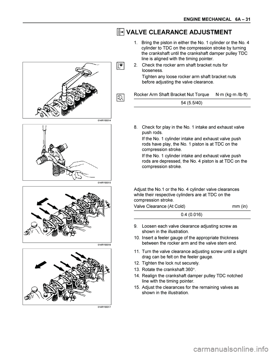
1. Bring the piston in either the No. 1 cylinder or the No. 4
cylinder to TDC on the compression stroke by turning
the crankshaft until the crankshaft damper pulley TDC
line is aligned with the timing pointer.
014RY00014
2. Check the rocker arm shaft bracket nuts for
looseness.
Tighten any loose rocker arm shaft bracket nuts
before adjusting the valve clearance.
Rocker Arm Shaft Bracket Nut Torque N·m (kg·m /lb·ft)
54 (5.5/40)
014RY00015
8. Check for play in the No. 1 intake and exhaust valve
push rods.
If the No. 1 cylinder intake and exhaust valve push
rods have play, the No. 1 piston is at TDC on the
compression stroke.
If the No. 1 cylinder intake and exhaust valve push
rods are depressed, the No. 4 piston is at TDC on the
compression stroke.
014RY00016
Adjust the No.1 or the No. 4 cylinder valve clearances
while their respective cylinders are at TDC on the
compression stroke.
Valve Clearance (At Cold) mm (in)
0.4 (0.016)
9. Loosen each valve clearance adjusting screw as
shown in the illustration.
10. Insert a feeler gauge of the appropriate thickness
between the rocker arm and the valve stem end.
014RY00017
11. Turn the valve clearance adjusting screw until a slight
drag can be felt on the feeler gauge.
12. Tighten the lock nut securely.
13. Rotate the crankshaft 360�.
14. Realign the crankshaft damper pulley TDC notched
line with the timing pointer.
15. Adjust the clearances for the remaining valves as
shown in the illustration.
Page 1174 of 4264
6A – 34 ENGINE MECHANICAL
RTW46ASH000701
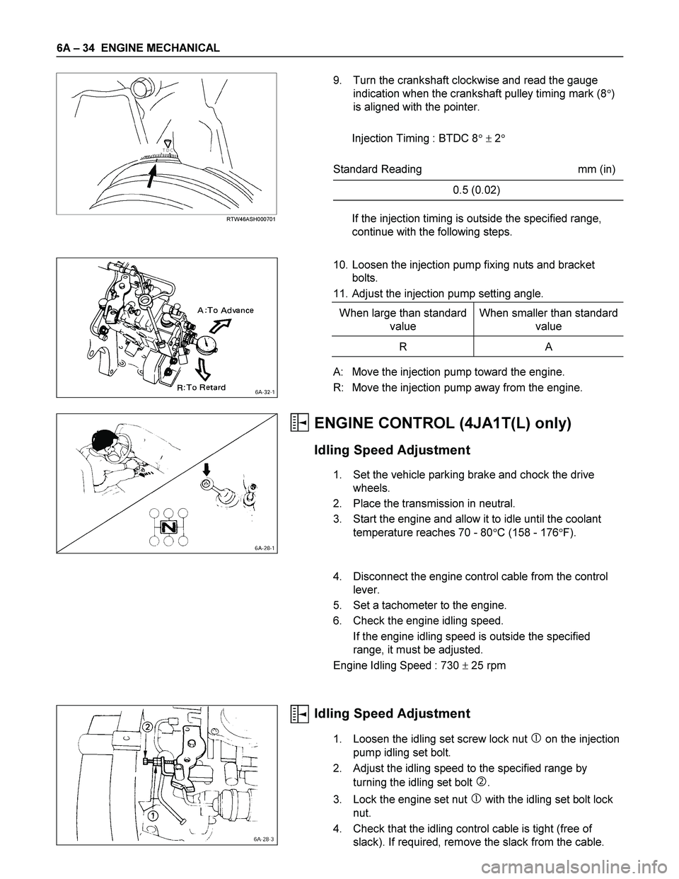
9. Turn the crankshaft clockwise and read the gauge
indication when the crankshaft pulley timing mark (8�)
is aligned with the pointer.
Injection Timing : BTDC 8� � 2�
Standard Reading mm (in)
0.5 (0.02)
If the injection timing is outside the specified range,
continue with the following steps.
10. Loosen the injection pump fixing nuts and bracket
bolts.
11. Adjust the injection pump setting angle.
When large than standard
value When smaller than standard
value
R A
A: Move the injection pump toward the engine.
R: Move the injection pump away from the engine.
ENGINE CONTROL (4JA1T(L) only)
Idling Speed Adjustment
1. Set the vehicle parking brake and chock the drive
wheels.
2. Place the transmission in neutral.
3. Start the engine and allow it to idle until the coolant
temperature reaches 70 - 80�C (158 - 176�F).
4. Disconnect the engine control cable from the control
lever.
5. Set a tachometer to the engine.
6. Check the engine idling speed.
If the engine idling speed is outside the specified
range, it must be adjusted.
Engine Idling Speed : 730 � 25 rpm
Idling Speed Adjustment
1. Loosen the idling set screw lock nut � on the injection
pump idling set bolt.
2. Adjust the idling speed to the specified range by
turning the idling set bolt
�.
3. Lock the engine set nut
� with the idling set bolt lock
nut.
4. Check that the idling control cable is tight (free of
slack). If required, remove the slack from the cable.
Page 1208 of 4264
6A – 68 ENGINE MECHANICAL
ROCKER ARM SHAFT AND ROCKER ARM
Rocker Arm Shaft Run-Out
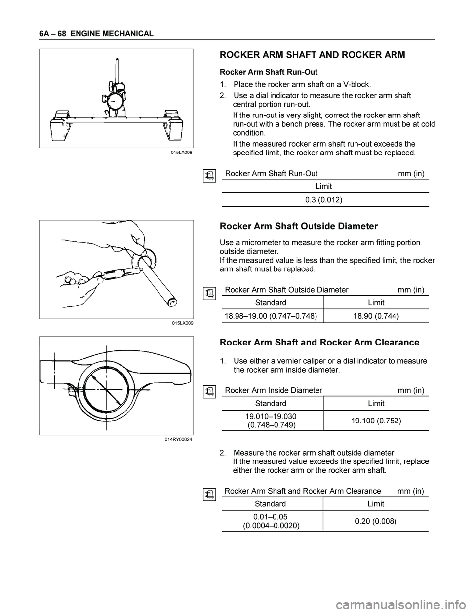
1. Place the rocker arm shaft on a V-block.
2. Use a dial indicator to measure the rocker arm shaft
central portion run-out.
If the run-out is very slight, correct the rocker arm shaft
run-out with a bench press. The rocker arm must be at cold
condition.
If the measured rocker arm shaft run-out exceeds the
specified limit, the rocker arm shaft must be replaced.
Rocker Arm Shaft Run-Out mm (in)
Limit
0.3 (0.012)
Rocker Arm Shaft Outside Diameter
Use a micrometer to measure the rocker arm fitting portion
outside diameter.
If the measured value is less than the specified limit, the rocker
arm shaft must be replaced.
Rocker Arm Shaft Outside Diameter mm (in)
Standard Limit
18.98–19.00 (0.747–0.748) 18.90 (0.744)
Rocker Arm Shaft and Rocker Arm Clearance
1. Use either a vernier caliper or a dial indicator to measure
the rocker arm inside diameter.
Rocker Arm Inside Diameter mm (in)
Standard Limit
19.010–19.030
(0.748–0.749) 19.100 (0.752)
2. Measure the rocker arm shaft outside diameter.
If the measured value exceeds the specified limit, replace
either the rocker arm or the rocker arm shaft.
Rocker Arm Shaft and Rocker Arm Clearance mm (in)
Standard Limit
0.01–0.05
(0.0004–0.0020) 0.20 (0.008)
015LX009
014RY00024015LX008