Page 1313 of 4264

FUEL SYSTEM 6C – 13
Removal
CAUTION: When repair to the fuel system has been
completed, start engine and check the fuel system for
loose connection or leakage. For the fuel system
diagnosis, see Section “Driveability and Emission".
1. Remove fuel tank assembly (9). Refer to “Fuel Tank
Removal" in this section.
2. Disconnect the quick connector (6) of the fuel tube from fuel
gauge unit.
3. Disconnect the quick connector (10) of the evapo tube from
fuel gauge unit.
140R100035
3. Remove the retainer ring (7) from the fuel tank with the
removal tool 5-8840-2602-0.
4.
Remove slowly the fuel gauge unit (4) from the fuel tank as
no bend float arm.
NOTE: Cover opening for the fuel gauge unit on fuel tank to
prevent any dust entering.
5.
Discard fuel gauge unit seal (8) because it cannot be
reusable.
Installation
1. Clean the seal surface of the fuel tank and the fuel gauge
unit.
NOTE: If there is dust on the seal surface, it becomes cause o
f
fuel leak.
2. Install the new fuel gauge unit seal (8) to opening of the fuel
tank as along the groove.
3. Install slowly the fuel gauge unit (4) into the fuel tank as no
bend float arm.
4.
Set flange of the fuel gauge unit on fuel gauge unit seal as
mating convexity of the fuel gauge unit and reentrant of the
fuel tank.
5.
Lock slowly the retainer ring (7) to the fuel tank with the
remover tool 5-8840-2602-0.
6. Connect the quick connector (10) of the evapo tube from
fuel gauge unit.
7.
Connect the quick connector (6) of the fuel tube to to gauge
unit.
NOTE: Pull off the left ckecker of the fuel pipe.
NOTE: Refer to “Fuel Tube/Quick Connector Fittings” in this
section when performing any repairs.
Page 1316 of 4264

6C – 16 FUEL SYSTEM
140R100037
2. For removal of the quick connector, hold the quick
connector in one hand, and pull out the connector with the
other hand while pressing the square relieve button of the
connector, as illustrated.
NOTE: Do not use tools of any kind. Only use bare hands
when disconnecting the connector. Use a lubricant (light oil)
and/or push and pull the connector until the pipe is
disconnected.
140R100028
Cover the connectors that was removed with a plastic bag,
to prevent dust or rain water from entering.
140R100036
Reuse of Quick–Connector
�
Replace the port and connector if scratch, dent or crack is
found.
� Remove any dirt build up on the port when installing the
connector. Replace the connector, if there is any forms o
f
rust, dent, scratch.
�
After cleaning the port, insert it straight into the connector
until it clicks. After it clicks, try pulling at 49N (5kgf) it out to
make sure that it is not drawn and is securely locked.
Assembling Advice
By applying engine oil or light oil to the pipe, port makes pipe
assembly easier. The pipe assembly should take place
immediately after applying oil (to prevent dust from sticking to
the pipe surface – which may decrease sealing ability).
Test/Inspection After Assembling
1. Reconnect the battery negative cable.
2. Start the engine and observe the engine idle speed. The
presence of dirt in the fuel system may affect the fuel
injection system.
3. Check for fuel leakage from the connector.
Page 1321 of 4264
FUEL SYSTEM 6C – 21
020L200017
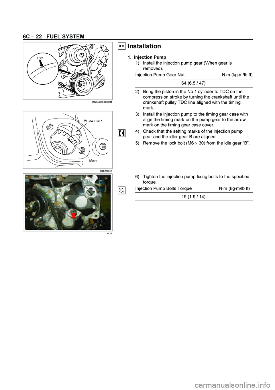
RTW46CSH000201
18. Timing Check Hole Cover
1) Remove the timing check hole cover.
2) For ease in reinstalling the injection pump, align the
timing mark on the timing gear case cover by turning
the crankshaft using wrench.
And bring the piston in the No.1 cylinder to TDC on the
compression stroke by turning the crankshaft until the
crankshaft pulley TDC line aligned with the timing
mark.
Note:
If the check hole cover is reinstalled with the lock bolt
still in place, the crank pulley will not turn.
6C-7
3) Insert the lock bolt (M6 x 30) into the scissors gear idle
gear “B” fixing hole to prevent the scissors gear from
turning.
29. Injection Pump Bracket
20. Injection Pump
Page 1322 of 4264
6C – 22 FUEL SYSTEM
RTW46CSH000201
Installation��
1. Injection Pump
1) Install the injection pump gear (When gear is
removed).
Injection Pump Gear Nut N�
m (kg�
m/lb ft)
64 (6.5 / 47)
2) Bring the piston in the No.1 cylinder to TDC on the
compression stroke by turning the crankshaft until the
crankshaft pulley TDC line aligned with the timing
mark.
020L200017
3) Install the injection pump to the timing gear case with
align the timing mark on the pump gear to the arrow
mark on the timing gear case cover.
4) Check that the setting marks of the injection pump
gear and the idler gear B are aligned.
5) Remove the lock bolt (M6 �
30) from the idle gear “B”.
6C-7
6) Tighten the injection pump fixing bolts to the specified
torque.
Injection Pump Bolts Torque N·m (kg·m/lb ft)
19 (1.9 / 14)
Page 1340 of 4264
6D – 2 ENGINE ELECTRICAL
MAIN DATA AND SPECIFICATIONS
Description
Item
60A 80A
Generator
Type
AC generator with IC regulator and vacuum pump
Hitachi LR160-503E Hitachi LR180-513B
Voltage V
Drive and rotation
Ground polarity 12
V-belt, clockwise viewed from the drive pulley
Negative
Maximum output A 60 80
Engine speed ratio to 1 1.788
Maximum speed rpm 11,000
Weight with vacuum pump kg(lb) 5.8(12.8) 6.4(14.1)
Vacuum Pump
Delivery volume cm3/rev
Exhaust Characteristic
Maximum vacuum
50
-66.7 kPa (-500 mmHg) bulid up time 21 seconds or less at 1,000
rpm
7 seconds or less at 5,000 rpm
-90.7 kPa (-680 mmHg) or more
Starter Motor
Type
Solenoid controlled
Hitachi S13-555
12
2.3
8.76
300 Rated voltage V
Rated output kW
Load characteristics
Terminal voltage V
Load current A
Weight kg(Ib)
4.7 (10.4)
Page 1366 of 4264
.
Replace the brushes as a set if one or more of the
brush lengths is less")
6D – 28 ENGINE ELECTRICAL
BRUSH AND BRUSH HOLDER
1. Use a vernier caliper to measure the brush length (four
brushes).
Replace the brushes as a set if one or more of the
brush lengths is less than the specified limit.
Brush Length mm (in)
Standard Limit
15 (0.59) 12 (0.47)
RTW46DSH004001
RTW46DSH004101
2. Use a circuit tester to check the brush holder
insulation.
Touch one probe to the holder plate and the other
probe to the positive brush holder.
There should be no continuity.
3. Inspect the brushes for excessive wear.
If the negative brushes have excessive wear, the
entire brush holder assembly must be replaced.
If the positive brushes have excessive wear, the entire
yoke must be replaced.
OVERRUNNING CLUTCH
1. Inspect the overrunning clutch gear teeth for
excessive wear and damage.
Replace the overrunning clutch if necessary.
2. Rotate the pinion clockwise.
It should turn smoothly.
3. Try to rotate the pinion in the opposite direction.
The pinion should lock.
065RY00035
RTW46DSH004401
BEARING
Inspect the bearings for excessive wear and damage.
Replace the bearings if necessary.
Page 1417 of 4264
4JA1/4JH1 ENGINE DRIVEABILITY AND EMISSIONS 6E–45
FUSE A ND RELAY LOCATION (LHD & RHD)
FUSE
SLOW BLOW FUSE
RELAYNo. Capacity Indication on label No. Capacity Indication on label
1——12 15A CIGER
2 10A ABS 13 15A AUDIO (+B)
3——14 20A DOOR LOCK
4 15A BACK UP 15 10A METER (+B)
5 15A METER 16 10A ROOM
6 10A TURN 17 10A ANTI THEFT
7 15A ELEC.IG 18 15A STOP
8 15A ENGINE 19 15A ACC SOCKET
9 20A FRT WIPER 20 10A STARTER
10 15A EGR 21 10A SRS
11 10A AUDIO
No. Capacity Indication on label
SBF-10 20A RR DEF
SBF-11 30A POWER WINDOW
Connector No. B-7 B-8 B-40
4JA1-TC, 4JH1-TC REAR
DEFOGGERPOWER
WINDOWACC
SOCKET
FUSE BOX
Page 1450 of 4264

6E–78 4JA1/4JH1 ENGINE DRIVEABILITY AND EMISSIONS
3. Check Bulletins and
Troubleshooting Hints
NOTE: As estimated 30 percent of successful vehicle
repairs are diagnosed with this step!
What you should do
You should have enough information gained from
preliminary checks to accurately search for a bulletin
and other related service information. Some service
manual sections provide troubleshooting hints that
match symptoms with specific complaints.
What resources you should use
You should use the following resources for assistance in
checking for bulletins and troubleshooting hints:
Printed bulletins
Access ISUZU Bulletin Web site.
Videotapes
Service manual
4. Perform Service Manual
Diagnostic Checks
What you should do
The “System Checks” in most service manual sections
and in most cells of section 8A (electrical) provide you
with:
A systematic approach to narrowing down the
possible causes of a system fault
Direction to specific diagnostic procedures in the
service manual
Assistance to identify what systems work correctly
What resources you should use
Whenever possible, you should use the following
resources to perform service manual checks:
Service manual
Technical equipment (for viewing DTCs and
analyzing data)
Digital multimeter and circuit testing tools
Other tools as needed
5a and 5b. Perform Service Manual
Diagnostic Procedures
NOTE: An estimated 40 percent of successful vehicle
repairs are diagnosed with these steps!
What you should do
When directed by service manual diagnostic checks,
you must then carefully and accurately perform the
steps of diagnostic procedures to locate the fault relatedto the customer complaint.
What resources you should use
Whenever appropriate, you should use the following
resources to perform service manual diagnostic
procedures:
Service manual
Technical equipment (for analyzing diagnostic data)
Digital multimeter and circuit testing tools
Essential and special tools
5c. Technician Self Diagnoses
When there is no DTC stored and no matching
symptom for the condition identified in the service
manual, you must begin with a thorough understanding
of how the system(s) operates. Efficient use of the
service manual combined with you ex perience and a
good process of elimination will result in accurate
diagnosis of the condition.
What you should do
Step 1: Identify and understand the suspect
circuit(s)
Having completed steps 1 through 4 of the Strategy
Based Diagnostics chart, you should have enough
information to identify the system(s) or sub-system(s)
involved. Using the service manual, you should
determine and investigate the following circuit
characteristics:
Electrical:
–How is the circuit powered (power distribution
charts and/or fuse block details)?
–How is the circuit grounded (ground distribution
charts)?
–How is the circuit controlled or sensed (theory of
operation):
–If it is a switched circuit, is it normally open or
normally closed?
–Is the power switched or is the ground
switched?
–Is it a variable resistance circuit (ECT sensor
or TP sensor, for ex ample)?
–Is it a signal generating device (MAF sensor of
VSS, for example)?
–Does it rely on some mechanical/vacuum
device to operate?
Physical:
–Where are the circuit components (component
locators and wire harness routing diagrams):
–Are there areas where wires could be chafed
or pinched (brackets or frames)?
–Are there areas subjected to ex treme
temperatures?
 Remove the timing check hole cover.
2) For ease in reinstalling the injection pump, align the
t")


FUSE
SLOW BLOW FUSE
RELAYNo. Capacity Indication on label No. Capacity Indication on label
1——12 15A CIGER")