UNIT REPAIR (JR405E) 7A4-21
No. Valve
nomenclature Diameter
(mm / in) Length
(mm / in)Configuration
1 Manual 12.0 /
0.472 82.0 /
3.228
2 2 – 4 brake
accumulator 15.0 /
0.591 37.5 /
1.476
3 Low and reverse
brake fail (B) 10.0 /
0.394 52.0 /
2.047
4 Reverse stall 8.0 /
0.315 50.0 /
1.969
5 Low and reverse
brake solenoid
accumulator 14.0 /
0.551 19.5 /
0.768
6 Pilot 12.0 /
0.472 38.5 /
1.516
7 Low clutch
solenoid
accumulator 14.0 /
0.551 19.5 /
0.768
8 Low clutch amp
(A) 12.0 /
0.472 53.5 /
2.106
9 2 – 4 brake fail
(B) 10.0 /
0.394 39.0 /
1.535
10 Lock-up control 12.9 /
0.508 57.5 /
2.264
11 2 – 4 brake amp 12.0 /
0.472 53.5 /
2.106
7A4-22 UNIT REPAIR (JR405E)
12 High clutch amp 12.0 /
0.472 53.5 /
2.106
13 High clutch
solenoid
accumulator 14.0 /
0.551 19.5 /
0.768
Spring specifications
No. Valve nomenclature Free length
(mm / in) Outside
diameter (mm
/ in) Linear
diameter (mm
/ in) Number of
coils
1 Manual ---- ---- ---- ----
2 2 – 4 brake accumulator 43.9 / 1.728 11.0 / 0.433 2.0 / 0.079 13.1
3 Low and reverse brake fail (B) 22.0 / 0.866 7.0 / 0.276 0.6 / 0.024 10.0
4 Reverse stall 31.5 / 1.240 7.0 / 0.276 1.0 / 0.039 12.8
5 Low and reverse solenoid brake
accumulator 31.4 / 1.236 9.8 / 0.386 1.3 / 0.051 9.3
6 Pilot 32.0 / 1.260 11.0 / 0.433 1.3 / 0.051 9.2
7 Low clutch solenoid accumulator 31.4 / 1.236 9.8 / 0.386 1.3 / 0.051 9.3
8 Low clutch amp (A) 23.0 / 0.906 11.0 / 0.433 0.5 / 0.020 13.2
9 2 – 4 brake fail (B) 24.8 / 0.976 8.5 / 0.335 0.9 / 0.035 7.8
10 Lock-up control 27.0 / 1.063 14.0 / 0.551 1.1 / 0.043 5.7
11 2 – 4 brake amp 23.0 / 0.906 11.0 / 0.433 0.5 / 0.020 13.2
12 High clutch amp 23.0 / 0.906 11.0 / 0.433 0.5 / 0.020 13.2
13 High clutch solenoid accumulator 31.4 / 1.236 9.8 / 0.386 1.3 / 0.051 9.3
Reassembly steps
� Coat the parts with ATF before installing them.
� Install the control valve to the upper body.
� Install the 11 steel balls and spring to the upper body.
UNIT REPAIR (JR405E) 7A4-23
CONTROL VALVE LOWER BODY
10CV11
Legend
1. Retainer plate, spring, and steel ball
2. Retainer plate, plug, spring, and
pressure regulator valve
3. Retainer plate, spring, and high clutch
accumulator
4. Retainer plate, plug, low and reverse
brake fail valve A, and spring
5. Retainer plate, plug, spring, and fail
valve
6. Retainer plate, plug, low and reverse
brake amp valve, and spring
7. Oil pressure switch
8. Oil filter
9. Solenoid
10. Line pressure solenoid
11. Lock-up solenoid
12. Harness bracket
13. Solenoid fixing plate
14. Harness assembly
15. Retainer plate, plug, spring, and 2-4
brake fail valve A
16. Retainer plate, plug, spring, and low
clutch amp valve B
17. Retainer plate, spring, and torque
converter relief valve
18. Oil strainer
19. Control valve lower body
20. Retainer plate, spring, and 2-4 brake
solenoid accumulator
21. Oil pressure switch
UNIT REPAIR (JR405E) 7A4-35
Return spring � Check the number of effective return spring coils.
If the number is less than the specified minimum, the
return spring must be replaced.
Effective return spring coils (standard): 10.2
� Measure the return spring outside diameter, free length,
and linear diameter.
If any of the measured values exceed the specified limit,
the return spring must be replaced.
Return spring measurements (standard):
Outside diameter – 8.0 mm (0.315 in)
Free length – 27.1 mm (1.067 in)
Linear diameter – 1.1 mm (0.043 in)
10R&H40
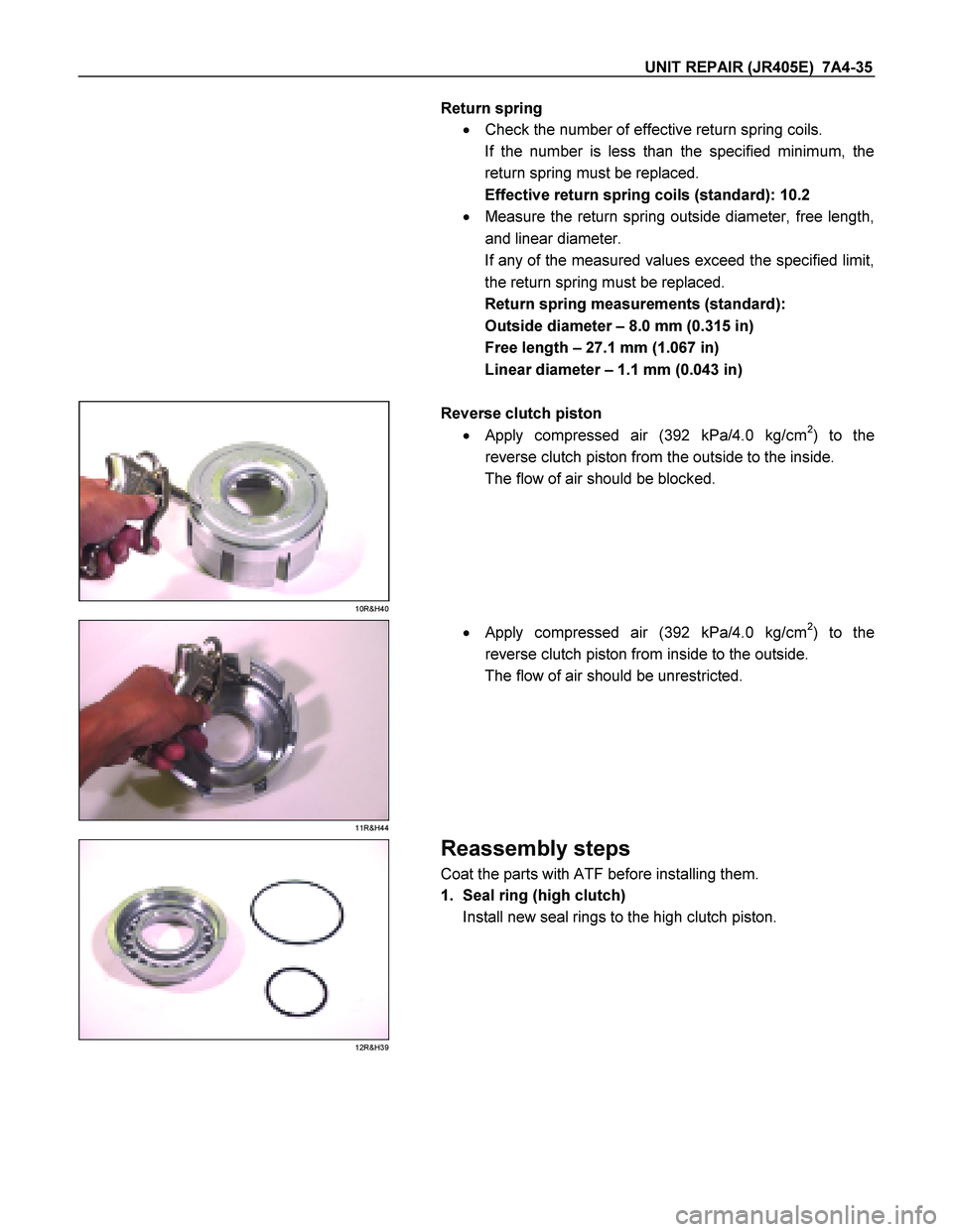
Reverse clutch piston
� Apply compressed air (392 kPa/4.0 kg/cm
2) to the
reverse clutch piston from the outside to the inside.
The flow of air should be blocked.
11R&H44
�
Apply compressed air (392 kPa/4.0 kg/cm2) to the
reverse clutch piston from inside to the outside.
The flow of air should be unrestricted.
12R&H39
Reassembly steps
Coat the parts with ATF before installing them.
1. Seal ring (high clutch)
Install new seal rings to the high clutch piston.
7A4-48 UNIT REPAIR (JR405E)
25C&L-SUB27
4. Side plate
Install the side plate.
26C&L-SUB26
5. Snap ring
Install the snap ring to the low clutch drum.
27C&L-SUB58
�
Attach the low one-way clutch inner race to the low
clutch drum in the opposite direction of normal position.
� Rotate the one-way clutch inner race clockwise. I
t
should turn smoothly with little resistance.
� Rotate the low one-way clutch inner race
counterclockwise.
It should immediately lock (rotation is impossible).
If it does not, check the low one-way clutch installation
direction.
Inspect and replace the low one-way clutch if required.
� Remove the low one-way clutch inner race.
� Reverse the low clutch drum.
28C&L-SUB32
6. Low clutch piston
� Install new seal rings to the low clutch piston.
 7A4-21
No. Valve
nomenclature Diameter
(mm / in) Length
(mm / in)Configuration
1 Manual 12.0 /
0.472 82.0 /
3.228
2 2 – 4 brake
accumulator 15.0 /
0.591 37.5 /
1.476")

12 High clutch amp 12.0 /
0.472 53.5 /
2.106
13 High clutch
solenoid
accumulator 14.0 /
0.551 19.5 /
0.768
Spring specifications
No. Valve nomenclature Free")
 7A4-23
CONTROL VALVE LOWER BODY
10CV11
Legend
1. Retainer plate, spring, and steel ball
2. Retainer plate, plug, spring, and
pressure regulator valve
3. Retain")

25C&L-SUB27
4. Side plate
Install the side plate.
26C&L-SUB26
5. Snap ring
Install the snap ring to the low clutch drum.
27C&L-SUB58")