2004 ISUZU TF SERIES lock
[x] Cancel search: lockPage 1694 of 4264
6E–322 4JA1/4JH1 ENGINE DRIVEABILITY AND EMISSIONS
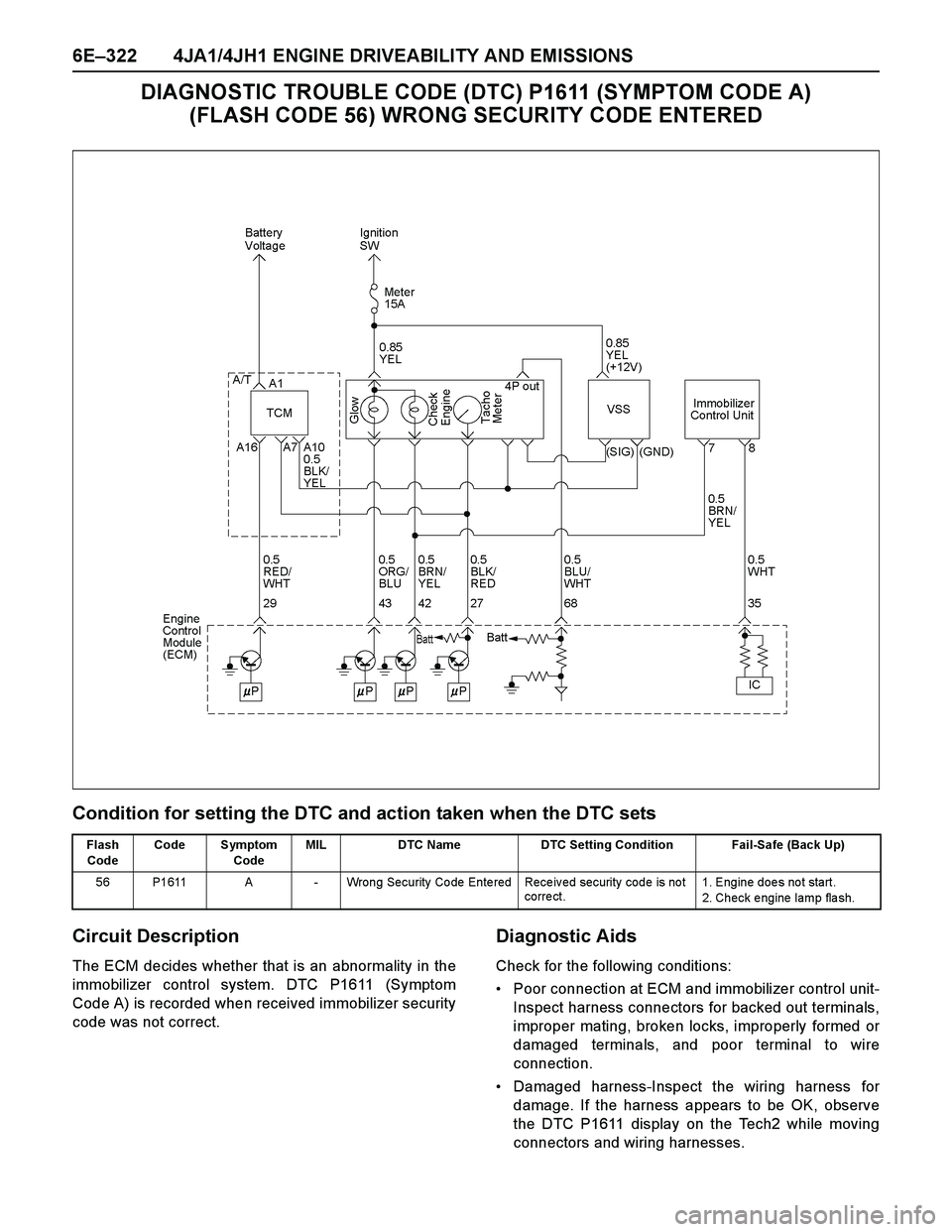
DIAGNOSTIC TROUBLE CODE (DTC) P1611 (SYMPTOM CODE A)
(FLASH CODE 56) WRONG SECURITY CODE ENTERED
Condition for setting the DTC and action taken when the DTC sets
Circuit Description
The ECM decides whether that is an abnormality in the
immobilizer control system. DTC P1611 (Symptom
Code A) is recorded when received immobilizer security
code was not correct.
Diagnostic Aids
Check for the following conditions:
Poor connection at ECM and immobilizer control unit-
Inspect harness connectors for backed out terminals,
improper mating, broken locks, improperly formed or
damaged terminals, and poor terminal to wire
connection.
Damaged harness-Inspect the wiring harness for
damage. If the harness appears to be OK, observe
the DTC P1611 display on the Tech2 while moving
connectors and wiring harnesses.
Flash
CodeCode Symptom
CodeMIL DTC Name DTC Setting Condition Fail-Safe (Back Up)
56 P1611 A - Wrong Security Code Entered Received security code is not
corre ct.1. Engine does not start.
2. Check e ngine lamp fla sh.
Page 1696 of 4264
6E–324 4JA1/4JH1 ENGINE DRIVEABILITY AND EMISSIONS
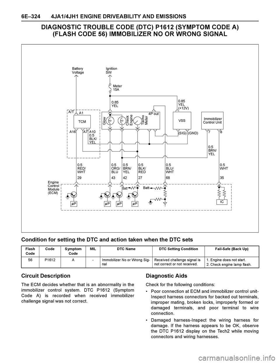
DIAGNOSTIC TROUBLE CODE (DTC) P1612 (SYMPTOM CODE A)
(FLASH CODE 56) IMMOBILIZER NO OR WRONG SIGNAL
Condition for setting the DTC and action taken when the DTC sets
Circuit Description
The ECM decides whether that is an abnormality in the
immobilizer control system. DTC P1612 (Symptom
Code A) is recorded when received immobilizer
challenge signal was not correct.
Diagnostic Aids
Check for the following conditions:
Poor connection at ECM and immobilizer control unit-
Inspect harness connectors for backed out terminals,
improper mating, broken locks, improperly formed or
damaged terminals, and poor terminal to wire
connection.
Damaged harness-Inspect the wiring harness for
damage. If the harness appears to be OK, observe
the DTC P1612 display on the Tech2 while moving
connectors and wiring harnesses.
Flash
CodeCode Symptom
CodeMIL DTC Name DTC Setting Condition Fail-Safe (Back Up)
56 P1612 A - Immobilizer No or Wrong Sig-
na lReceived challenge signal is
no t co rrect or not re ce iv ed.1. Engine does not start.
2. Check e ngine lamp fla sh.
Page 1702 of 4264
6E–330 4JA1/4JH1 ENGINE DRIVEABILITY AND EMISSIONS
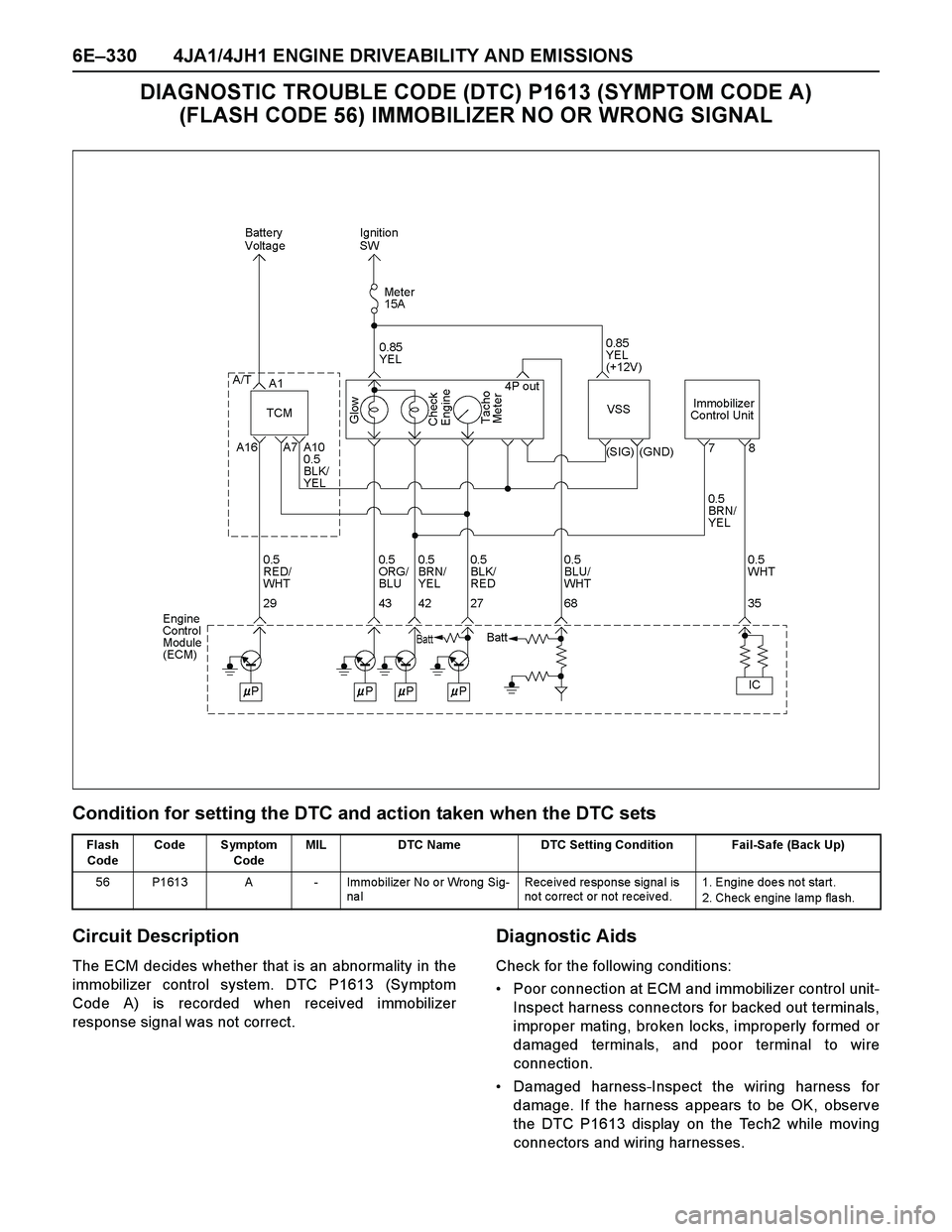
DIAGNOSTIC TROUBLE CODE (DTC) P1613 (SYMPTOM CODE A)
(FLASH CODE 56) IMMOBILIZER NO OR WRONG SIGNAL
Condition for setting the DTC and action taken when the DTC sets
Circuit Description
The ECM decides whether that is an abnormality in the
immobilizer control system. DTC P1613 (Symptom
Code A) is recorded when received immobilizer
response signal was not correct.
Diagnostic Aids
Check for the following conditions:
Poor connection at ECM and immobilizer control unit-
Inspect harness connectors for backed out terminals,
improper mating, broken locks, improperly formed or
damaged terminals, and poor terminal to wire
connection.
Damaged harness-Inspect the wiring harness for
damage. If the harness appears to be OK, observe
the DTC P1613 display on the Tech2 while moving
connectors and wiring harnesses.
Flash
CodeCode Symptom
CodeMIL DTC Name DTC Setting Condition Fail-Safe (Back Up)
56 P1613 A - Immobilizer No or Wrong Sig-
na lReceived response signal is
no t co rrect or not re ce iv ed.1. Engine does not start.
2. Check e ngine lamp fla sh.
Page 1707 of 4264
4JA1/4JH1 ENGINE DRIVEABILITY AND EMISSIONS 6E–335
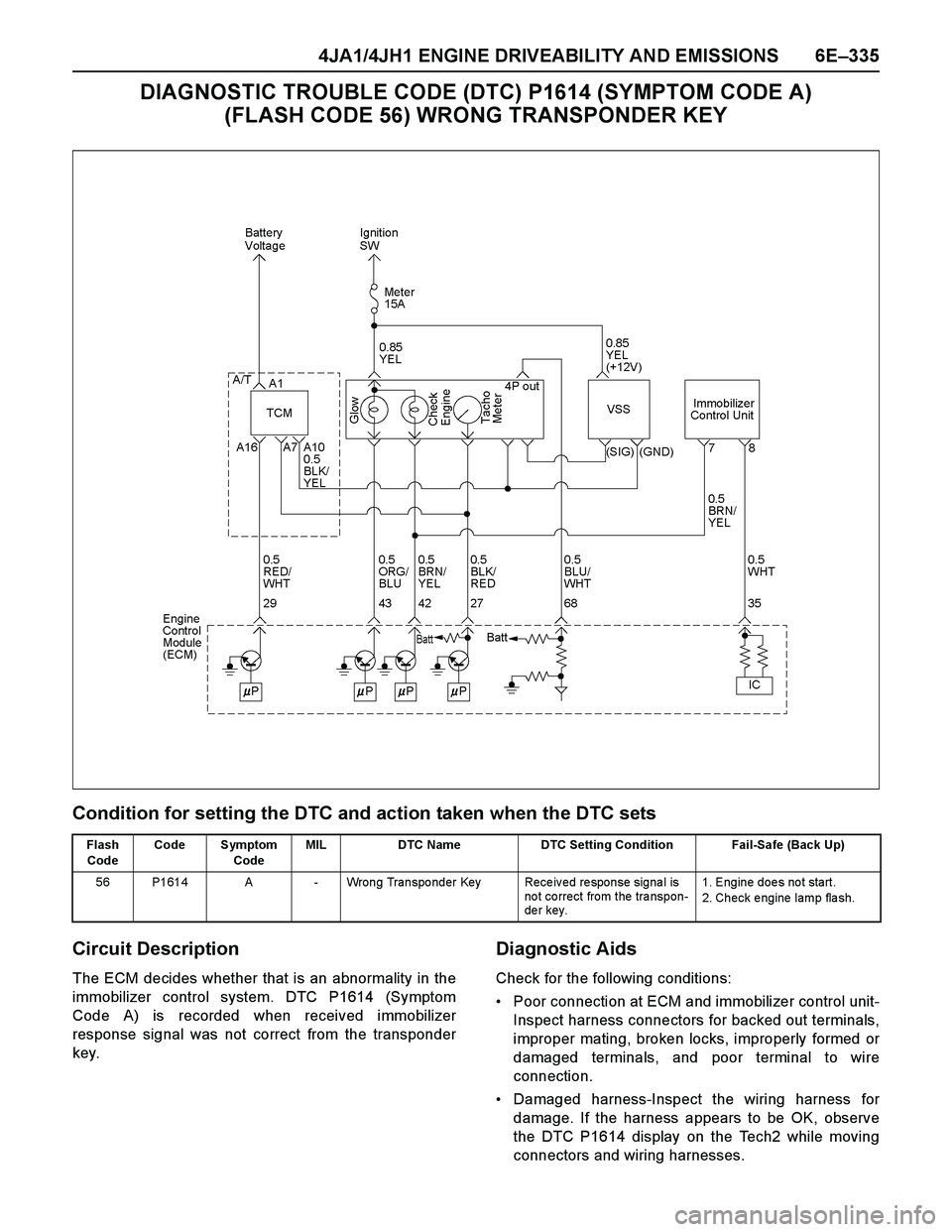
DIAGNOSTIC TROUBLE CODE (DTC) P1614 (SYMPTOM CODE A)
(FLASH CODE 56) WRONG TRANSPONDER KEY
Condition for setting the DTC and action taken when the DTC sets
Circuit Description
The ECM decides whether that is an abnormality in the
immobilizer control system. DTC P1614 (Symptom
Code A) is recorded when received immobilizer
response signal was not correct from the transponder
key.
Diagnostic Aids
Check for the following conditions:
Poor connection at ECM and immobilizer control unit-
Inspect harness connectors for backed out terminals,
improper mating, broken locks, improperly formed or
damaged terminals, and poor terminal to wire
connection.
Damaged harness-Inspect the wiring harness for
damage. If the harness appears to be OK, observe
the DTC P1614 display on the Tech2 while moving
connectors and wiring harnesses.
Flash
CodeCode Symptom
CodeMIL DTC Name DTC Setting Condition Fail-Safe (Back Up)
56 P1614 A - Wrong Transponder Key Received response signal is
not correct from the transpon-
der key.1. Engine does not start.
2. Check e ngine lamp fla sh.
Page 1710 of 4264
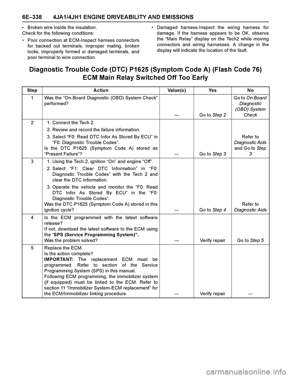
6E–338 4JA1/4JH1 ENGINE DRIVEABILITY AND EMISSIONS
Broken wire inside the insulation.
Check for the following conditions:
Poor connection at ECM-Inspect harness connectors
for backed out terminals, improper mating, broken
locks, improperly formed or damaged terminals, and
poor terminal to wire connection.Damaged harness-Inspect the wiring harness for
damage. If the harness appears to be OK, observe
the “Main Relay” display on the Tech2 while moving
connectors and wiring harnesses. A change in the
display will indicate the location of the fault.
Diagnostic Trouble Code (DTC) P1625 (Symptom Code A) (Flash Code 76)
ECM Main Relay Switched Off Too Early
Step Action Value(s) Yes No
1Was the “On-Board Diagnostic (OBD) System Check”
performed?
—Go to Step 2Go to On Board
Diagnostic
(OBD) System
Check
2 1. Connect the Tech 2.
2. Review and record the failure information.
3. Select “F0: Read DTC Infor As Stored By ECU” in
“F0: Diagnostic Trouble Codes”.
Is the DTC P1625 (Symptom Code A) stored as
“Present Failure”?—Go to Step 3Refer to
Diagnostic Aids
and Go to Step
3
3 1. Using the Tech 2, ignition “On” and engine “Off”.
2. Select “F1: Clear DTC Information” in “F0:
Diagnostic Trouble Codes” with the Tech 2 and
clear the DTC information.
3. Operate the vehicle and monitor the “F0: Read
DTC Infor As Stored By ECU” in the “F0:
Diagnostic Trouble Codes”.
Was the DTC P1625 (Symptom Code A) stored in this
ignition cycle?—Go to Step 4Refer to
Diagnostic Aids
4 Is the ECM programmed with the latest software
release?
If not, download the latest software to the ECM using
the “SPS (Service Programming System)”.
Was the problem solved?—Verify repair Go to Step 5
5 Replace the ECM.
Is the action complete?
IMPORTANT: The replacement ECM must be
programmed. Refer to section of the Service
Programming System (SPS) in this manual.
Following ECM programming, the immobilizer system
(if equipped) must be linked to the ECM. Refer to
section 11 “Immobilizer System-ECM replacement” for
the ECM/Immobilizer linking procedure.—Verify repair—
Page 1713 of 4264
4JA1/4JH1 ENGINE DRIVEABILITY AND EMISSIONS 6E–341
Diagnostic Aids
An intermittent may be caused by the following:
Poor connections.
Misrouted harness.
Rubbed through wire insulation.Broken wire inside the insulation.
Check for the following conditions:
Poor connection at ECM and PSG-Inspect harness
connectors for backed out terminals, improper
mating, broken locks, improperly formed or damaged
terminals, and poor terminal to wire connection.
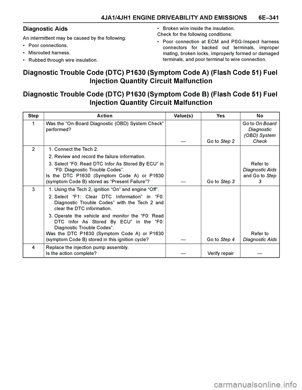
Diagnostic Trouble Code (DTC) P1630 (Sy mptom Code A) (Flash Code 51) Fuel
Injection Quantity Circuit Malfunction
Diagnostic Trouble Code (DTC) P1630 (Sy mptom Code B) (Flash Code 51) Fuel
Injection Quantity Circuit Malfunction
Step Action Value(s) Yes No
1Was the “On-Board Diagnostic (OBD) System Check”
performed?
—Go to Step 2Go to On Board
Diagnostic
(OBD) System
Check
2 1. Connect the Tech 2.
2. Review and record the failure information.
3. Select “F0: Read DTC Infor As Stored By ECU” in
“F0: Diagnostic Trouble Codes”.
Is the DTC P1630 (Symptom Code A) or P1630
(symptom Code B) stored as “Present Failure”?—Go to Step 3Refer to
Diagnostic Aids
and Go to Step
3
3 1. Using the Tech 2, ignition “On” and engine “Off”.
2. Select “F1: Clear DTC Information” in “F0:
Diagnostic Trouble Codes” with the Tech 2 and
clear the DTC information.
3. Operate the vehicle and monitor the “F0: Read
DTC Infor As Stored By ECU” in the “F0:
Diagnostic Trouble Codes”.
Was the DTC P1630 (Symptom Code A) or P1630
(symptom Code B) stored in this ignition cycle?—Go to Step 4Refer to
Diagnostic Aids
4 Replace the injection pump assembly.
Is the action complete?—Verify repair—
Page 1715 of 4264
4JA1/4JH1 ENGINE DRIVEABILITY AND EMISSIONS 6E–343
Poor connection at ECM and PSG-Inspect harness
connectors for backed out terminals, improper
mating, broken locks, improperly formed or damaged
terminals, and poor terminal to wire connection.Damaged harness-Inspect the wiring harness for
damage. If the harness appears to be OK, observe
the DTC P1650 display on the Tech2 while moving
connectors and wiring harnesses.
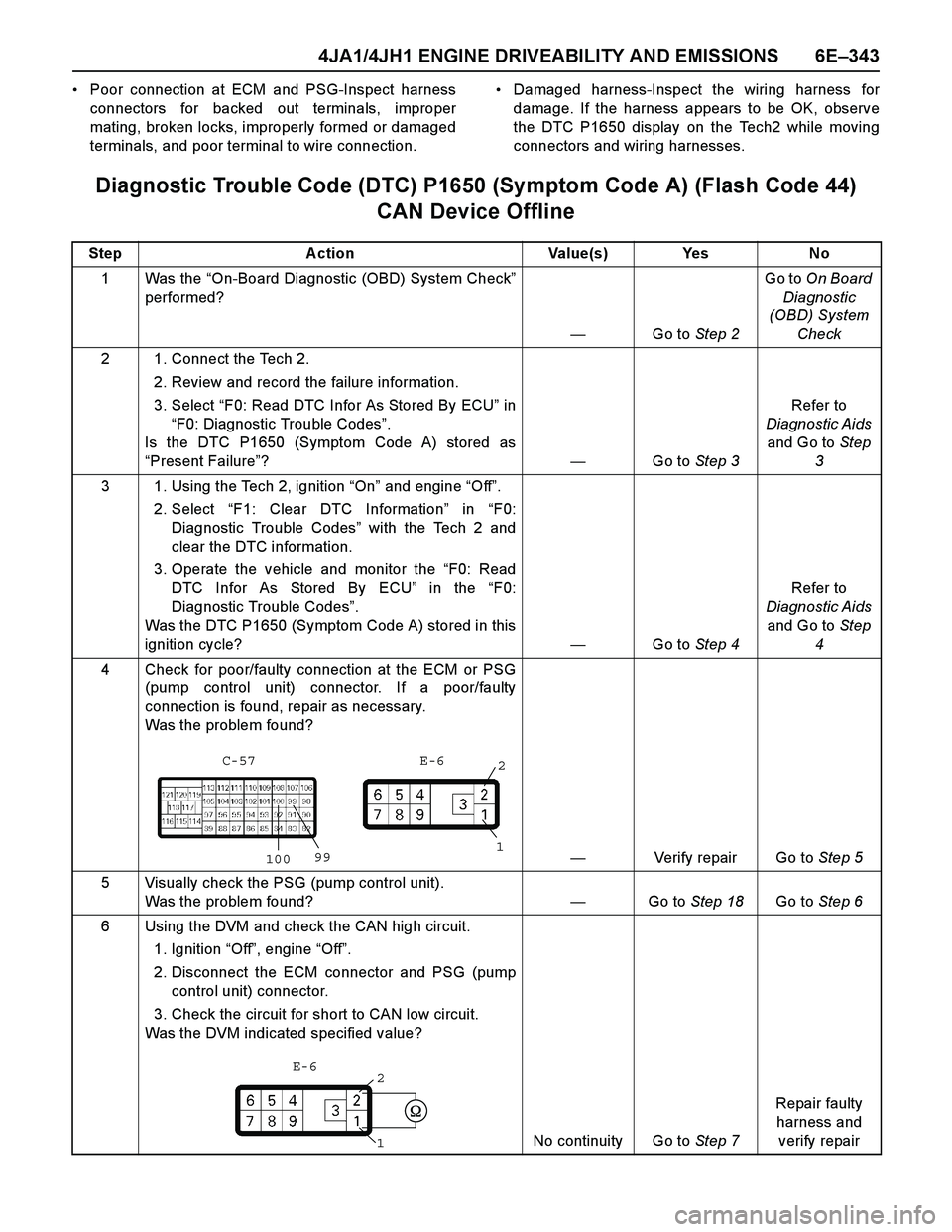
Diagnostic Trouble Code (DTC) P1650 (Symptom Code A) (Flash Code 44)
CAN Device Offline
Step Action Value(s) Yes No
1Was the “On-Board Diagnostic (OBD) System Check”
performed?
—Go to Step 2Go to On Board
Diagnostic
(OBD) System
Check
2 1. Connect the Tech 2.
2. Review and record the failure information.
3. Select “F0: Read DTC Infor As Stored By ECU” in
“F0: Diagnostic Trouble Codes”.
Is the DTC P1650 (Symptom Code A) stored as
“Present Failure”?—Go to Step 3Refer to
Diagnostic Aids
and Go to Step
3
3 1. Using the Tech 2, ignition “On” and engine “Off”.
2. Select “F1: Clear DTC Information” in “F0:
Diagnostic Trouble Codes” with the Tech 2 and
clear the DTC information.
3. Operate the vehicle and monitor the “F0: Read
DTC Infor As Stored By ECU” in the “F0:
Diagnostic Trouble Codes”.
Was the DTC P1650 (Symptom Code A) stored in this
ignition cycle?—Go to Step 4Refer to
Diagnostic Aids
and Go to Step
4
4 Check for poor/faulty connection at the ECM or PSG
(pump control unit) connector. If a poor/faulty
connection is found, repair as necessary.
Was the problem found?
—Verify repair Go to Step 5
5 Visually check the PSG (pump control unit).
Was the problem found? —Go to Step 18Go to Step 6
6 Using the DVM and check the CAN high circuit.
1. Ignition “Off”, engine “Off”.
2. Disconnect the ECM connector and PSG (pump
control unit) connector.
3. Check the circuit for short to CAN low circuit.
Was the DVM indicated specified value?
No continuity Go to Step 7Repair faulty
harness and
verify repair
1009912
C-57 E-6
2
1E-6
Page 1722 of 4264
6E–350 4JA1/4JH1 ENGINE DRIVEABILITY AND EMISSIONS
Rubbed through wire insulation.
Broken wire inside the insulation.
Check for the following conditions:
Poor connection at ECM and PSG-Inspect harness
connectors for backed out terminals, improper
mating, broken locks, improperly formed or damagedterminals, and poor terminal to wire connection.
Damaged harness-Inspect the wiring harness for
damage. If the harness appears to be OK, observe
the DTC P1651 display on the Tech2 while moving
connectors and wiring harnesses.
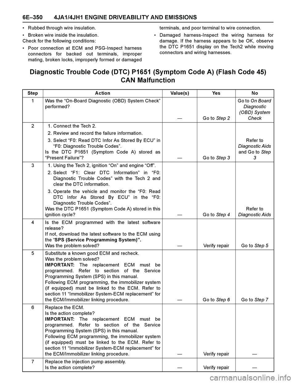
Diagnostic Trouble Code (DTC) P1651 (Symptom Code A) (Flash Code 45)
CAN Malfunction
Step Action Value(s) Yes No
1Was the “On-Board Diagnostic (OBD) System Check”
performed?
—Go to Step 2Go to On Board
Diagnostic
(OBD) System
Check
2 1. Connect the Tech 2.
2. Review and record the failure information.
3. Select “F0: Read DTC Infor As Stored By ECU” in
“F0: Diagnostic Trouble Codes”.
Is the DTC P1651 (Symptom Code A) stored as
“Present Failure”?—Go to Step 3Refer to
Diagnostic Aids
and Go to Step
3
3 1. Using the Tech 2, ignition “On” and engine “Off”.
2. Select “F1: Clear DTC Information” in “F0:
Diagnostic Trouble Codes” with the Tech 2 and
clear the DTC information.
3. Operate the vehicle and monitor the “F0: Read
DTC Infor As Stored By ECU” in the “F0:
Diagnostic Trouble Codes”.
Was the DTC P1651 (Symptom Code A) stored in this
ignition cycle?—Go to Step 4Refer to
Diagnostic Aids
4 Is the ECM programmed with the latest software
release?
If not, download the latest software to the ECM using
the “SPS (Service Programming System)”.
Was the problem solved?—Verify repair Go to Step 5
5 Substitute a known good ECM and recheck.
Was the problem solved?
IMPORTANT: The replacement ECM must be
programmed. Refer to section of the Service
Programming System (SPS) in this manual.
Following ECM programming, the immobilizer system
(if equipped) must be linked to the ECM. Refer to
section 11 “Immobilizer System-ECM replacement” for
the ECM/Immobilizer linking procedure. —Go to Step 6Go to Step 7
6 Replace the ECM.
Is the action complete?
IMPORTANT: The replacement ECM must be
programmed. Refer to section of the Service
Programming System (SPS) in this manual.
Following ECM programming, the immobilizer system
(if equipped) must be linked to the ECM. Refer to
section 11 “Immobilizer System-ECM replacement” for
the ECM/Immobilizer linking procedure.—Verify repair—
7 Replace the injection pump assembly.
Is the action complete?—Verify repair—