Page 1324 of 4264

29 (3.0 / 22)
Nozzle Side (4JA1TC/4JH1TC) N·m(kg·m / lb ft)
29 (3.0")
6C – 24 FUEL SYSTEM
6. Injection Pipe
Install the injection pipe.
Injection Pipe Torque N·m(kg·m / lb ft)
29 (3.0 / 22)
Nozzle Side (4JA1TC/4JH1TC) N·m(kg·m / lb ft)
29 (3.0 / 22)
Pump Side (4JA1TC/4JH1TC) N·m(kg·m / lb ft)
40 (4.1 / 30)
7. Injection Pipe Clip
Install the injection pipe clip.
Note:
Make absolutely sure that the clip is correctly
positioned.
Injection Pipe Clip Torque N·m(kg·m / lb in)
8 (0.8 / 69)
8. Leak Off Pipe and Leak Off Hose
Install the leak off pipe to injection nozzle and connect the
leak off hose to the injection pump.
9. Fuel Filter Bracket (Except EURO III model)
Install the fuel filter bracket and tighten bolts to the
specified torque.
Fuel Filter Bracket Bolts Torque N·m(kg·m / lb ft)
21 (2.1 / 15)
10. Fuel Filter Assembly (Except EURO III model)
Install the fuel filter assembly to bracket and tighten bolts
to the specified torque.
Fuel Filter Assembly Bolts
Torque N·m(kg·m / lb ft)
21 (2.1 / 15)
11. Fuel Pipe
1) Connect the fuel hoses to the fuel filter or priming
pump.
2) Connect the fuel hoses to the injection pump.
12. Oil Level Gauge
Install the oil level gauge and tighten bolts to the specified
torque.
Oil Level Gauge Bolts
Torque N·m(kg·m / lb ft)
M8: 19 (1.9 / 14)
M6: 8 (0.8/6 lb in)
Page 1330 of 4264
6C – 30 FUEL SYSTEM
5. Install the pins in the spacer.
6. Install the nozzle on the spacer.
7. Hand-tighten the adjustment retaining nut together
with the gasket to the nozzle holder.
Retaining nut: 157892-3200 (Bosch AS)
Gasket: 157892-5100 (Bosch AS)
(Bosch AS = Bosch Automotive Systems Corporation)
8. Tighten the adjustment retaining nut to the specified
torque.
Torque: 5.1 kg·m (36.9 Ib·ft/50 N·m)
9. Set the nozzle holder to the nozzle tester.
10. Operate the nozzle tester and measure the first nozzle
opening pressure.
11. If the first nozzle opening pressure is not as specified,
disassemble the nozzle holder and replace the shim
until the pressure is as specified.
CAUTION:
Use a micrometer to measure shim thickness.
040MV019.tif
040MV010.ti
f
040MV014-1.tif
040MV030.ti
f
Page 1336 of 4264

6C – 36 FUEL SYSTEM
Second nozzle opening pressure adjustment
If the second nozzle opening pressure is not as specified,
disassemble the nozzle from the nozzle holder and
replace the shim until the pressure is as specified.
CAUTION:
Because the second opening pressure changes
when the first opening pressure changes, the
second opening pressure must be adjusted when
the first opening pressure changes.
Use a micrometer to measure shim thickness.
Use some combination of 3 adjusting shims to
adjust the pressure.
Second nozzle opening pressure adjusting shims
Part No.
(ISUZU) Thickness
(mm) Part No.
(ISUZU) Thickness
(mm)
897116-0290 0.10 897116-0380 0.53
897116-0320 0.20 897116-0390 0.54
897116-0330 0.30 897116-0400 0.55
897116-0340 0.40 897116-0410 0.56
897116-0350 0.50 897116-0420 0.57
897116-0360 0.51 897116-0430 0.58
897116-0370 0.52 897116-0440 0.59
Final inspection
1. Remove the dial gauge, nut and dial gauge holder.
2. Remove the adjustment retaining nut and gasket.
3. Install the original retaining nut, confirm that the pins
are inserted fully into the nozzle, and then hand-tighten
the retaining nut. Then, tighten the original retaining
nut to the specified torque.
Torque: 7.0 kg·m (50.6 Ib·ft/69 N·m)
040MV017.tif
040LX009.tif
040MV028.tif
040M V014-1.ti
f
Page 1339 of 4264

ENGINE ELECTRICAL 6D – 1
SECTION 6D
ENGINE ELECTRICAL
TABLE OF CONTENTS
PAGE
Main Data and Specifications ......................................................................................... 6D - 2
General Description......................................................................................................... 6D - 3
Torque Specifications ..................................................................................................... 6D - 5
Generator.......................................................................................................................... 6D - 7
Removal and Installation ............................................................................................ 6D - 7
Disassembly................................................................................................................. 6D - 9
Inspection and Repair ................................................................................................. 6D - 12
Reassembly.................................................................................................................. 6D - 18
Starter Motor .................................................................................................................... 6D - 22
Removal and Installation ............................................................................................ 6D - 22
Disassembly................................................................................................................. 6D - 23
Inspection and Repair ................................................................................................. 6D - 26
Reassembly.................................................................................................................. 6D - 29
Pre-heating System ......................................................................................................... 6D -33
Inspection and Repair ................................................................................................. 6D -33
Glow Relay ................................................................................................................... 6D -33
Glow Plug ..................................................................................................................... 6D -33
EGR System ................................................................................................................. 6D -33
Page 1343 of 4264
ENGINE ELECTRICAL 6D – 5
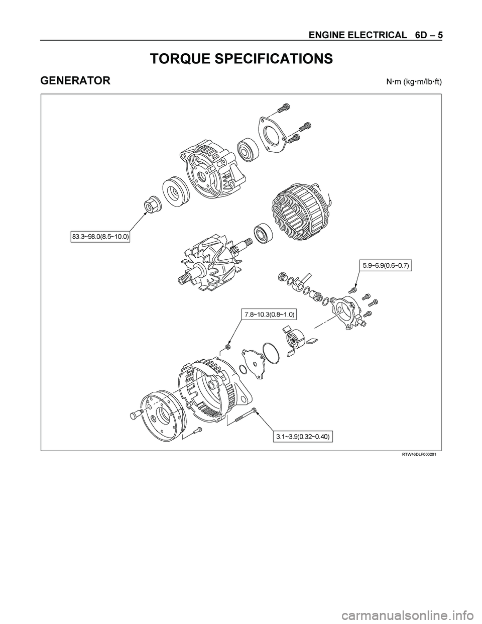
TORQUE SPECIFICATIONS
GENERATOR N�m (kg�m/Ib�ft)
RTW46DLF000201
Page 1345 of 4264

ENGINE ELECTRICAL 6D – 7
GENERATOR
REMOVAL AND INSTALLATION
Read this Section carefully before performing any removal and installation procedure. This Section gives you
important points as well as the order of operation. Be sure that you understand everything in this Section before you
begin.
P1010002
Important Operations-Removal
Cooling Fan Belt
1. Disconnect the battery cables at the battery terminals.
2. Loosen and remove the fan belt adjusting plate bolts.
3. Remove the fan belt from the generator drive pulley.
Generator
1. Remove the vacuum pump hose.
2. Remove the generator bolt and the generator from the bracket.
Important Operations-Installation
Follow the removal procedure in the reverse order to
perform the installation procedure. Pay careful attention to
the important points during the installation procedure.
Generator
1. Install the generator to the bracket.
2. Tighten the generator bolt to the specified torque.
3. Install the vacuum pump hose.
Generator Bolt Torque N �m (kg �m/Ib �ft)
40 (4.1/30)
Page 1346 of 4264
6D – 8 ENGINE ELECTRICAL
033RY00009
Cooling Fan Drive Belt
1. Hold the generator toward the engine.
2. Install the fan belt to the three pulleys.
1 Crankshaft pulley
2 Generator pulley
3 Cooling fan drive pulley
3. Adjust the fan belt tension
Fan belt tension is adjusted by moving the generator.
Depress the drive belt mid-portion with a 98N (10
kg/22 Ib) force.
Cooling Fan Drive Belt Deflection mm (in)
New belt 4 - 7 (0.16 - 0.28)
Reuse belt 6 - 9 (0.24 - 0.35)
4. Tighten the adjusting plate bolts to the specified
torque.
Adjusting Plate Bolt N·m (kg·m/lb·ft)
19 (1.9/14)
5. Reconnect the battery cable to the battery.
Page 1357 of 4264
ENGINE ELECTRICAL 6D – 19
RTW46DSH000401
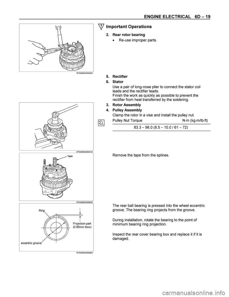
Important Operations
2. Rear rotor bearing
� Re-use improper parts.
5. Rectifier
6. Stator
Use a pair of long-nose plier to connect the stator coil
leads and the rectifier leads.
Finish the work as quickly as possible to prevent the
rectifier from heat transferred by the soldering.
RTW46DSH002101
3. Rotor Assembly
4. Pulley Assembly
Clamp the rotor in a vise and install the pulley nut.
Pulley Nut Torque N�m (kg�m/lb�ft)
83.3 � 98.0 (8.5 � 10.0 / 61 � 72)
RTW46DSH006001
Remove the tape from the splines.
RTW46DSH004901
The rear ball bearing is pressed into the wheel eccentric
groove. The bearing ring projects from the groove.
During installation, rotate the bearing to the point of
minimum bearing ring projection.
Inspect the rear cover bearing box and replace it if it is
damaged.