Page 1249 of 4264
ENGINE MECHANICAL 6A – 109
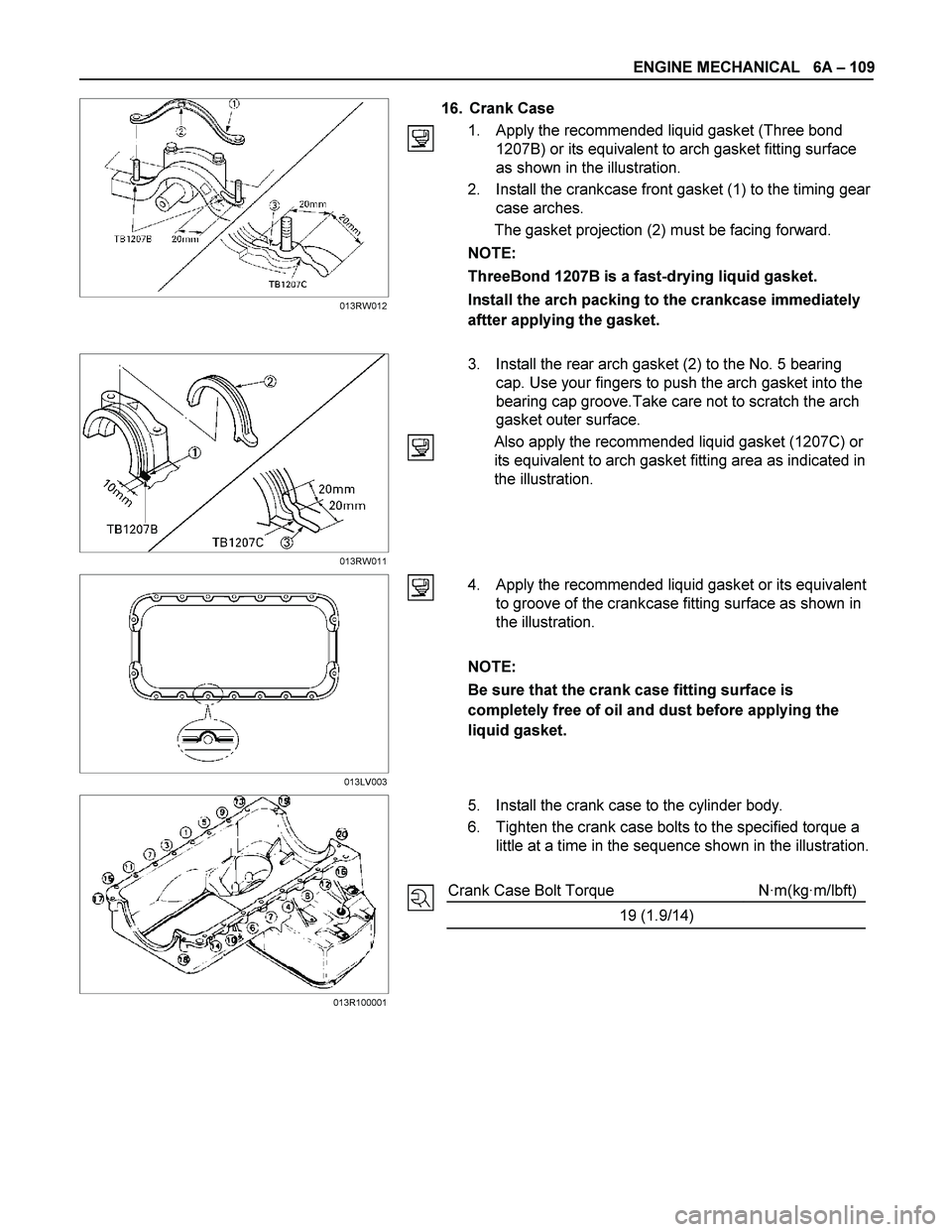
16. Crank Case
1. Apply the recommended liquid gasket (Three bond
1207B) or its equivalent to arch gasket fitting surface
as shown in the illustration.
2. Install the crankcase front gasket (1) to the timing gear
case arches.
The gasket projection (2) must be facing forward.
NOTE:
ThreeBond 1207B is a fast-drying liquid gasket.
Install the arch packing to the crankcase immediately
aftter applying the gasket.
3. Install the rear arch gasket (2) to the No. 5 bearing
cap. Use your fingers to push the arch gasket into the
bearing cap groove.Take care not to scratch the arch
gasket outer surface.
Also apply the recommended liquid gasket (1207C) or
its equivalent to arch gasket fitting area as indicated in
the illustration.
4. Apply the recommended liquid gasket or its equivalent
to groove of the crankcase fitting surface as shown in
the illustration.
NOTE:
Be sure that the crank case fitting surface is
completely free of oil and dust before applying the
liquid gasket.
5. Install the crank case to the cylinder body.
6. Tighten the crank case bolts to the specified torque a
little at a time in the sequence shown in the illustration.
Crank Case Bolt Torque N·m(kg·m/lbft)
19 (1.9/14)
013LV003 013RW012
013RW011
013R100001
Page 1250 of 4264
6A – 110 ENGINE MECHANICAL
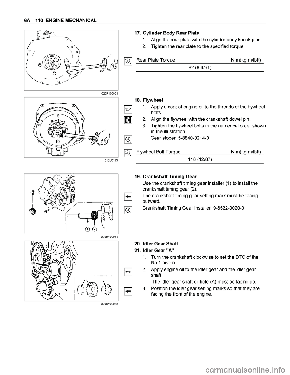
17. Cylinder Body Rear Plate
1. Align the rear plate with the cylinder body knock pins.
2. Tighten the rear plate to the specified torque.
Rear Plate Torque N·m(kg·m/lbft)
82 (8.4/61)
18. Flywheel
1. Apply a coat of engine oil to the threads of the flywheel
bolts.
2. Align the flywheel with the crankshaft dowel pin.
3. Tighten the flywheel bolts in the numerical order shown
in the illustration.
Gear stoper: 5-8840-0214-0
Flywheel Bolt Torque N·m(kg·m/lbft)
118 (12/87)
19. Crankshaft Timing Gear
Use the crankshaft timing gear installer (1) to install the
crankshaft timing gear (2).
The crankshaft timing gear setting mark must be facing
outward.
Crankshaft Timing Gear Installer: 9-8522-0020-0
20. Idler Gear Shaft
21. Idler Gear "A"
1. Turn the crankshaft clockwise to set the DTC of the
No.1 piston.
2. Apply engine oil to the idler gear and the idler gear
shaft.
The idler gear shaft oil hole (A) must be facing up.
3. Position the idler gear setting marks so that they are
facing the front of the engine.
015LX113 020R100001
020RY00034
020RY00035
Page 1251 of 4264
ENGINE MECHANICAL 6A – 111
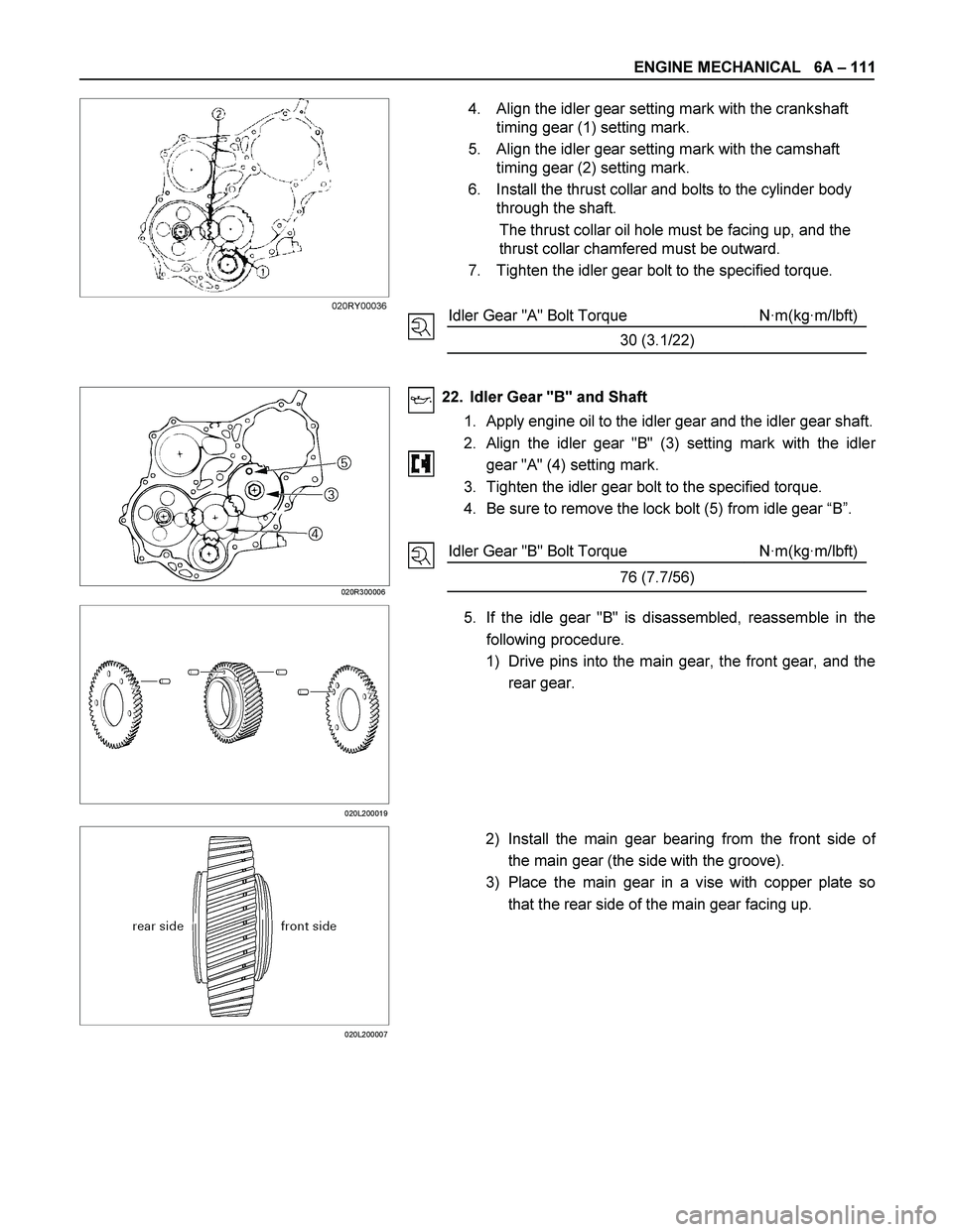
4. Align the idler gear setting mark with the crankshaft
timing gear (1) setting mark.
5. Align the idler gear setting mark with the camshaft
timing gear (2) setting mark.
6. Install the thrust collar and bolts to the cylinder body
through the shaft.
The thrust collar oil hole must be facing up, and the
thrust collar chamfered must be outward.
7. Tighten the idler gear bolt to the specified torque.
Idler Gear "A" Bolt Torque N·m(kg·m/lbft)
30 (3.1/22)
020R300006
22. Idler Gear "B" and Shaft
1. Apply engine oil to the idler gear and the idler gear shaft.
2.
Align the idler gear "B" (3) setting mark with the idler
gear "A" (4) setting mark.
3. Tighten the idler gear bolt to the specified torque.
4. Be sure to remove the lock bolt (5) from idle gear “B”.
Idler Gear "B" Bolt Torque N·m(kg·m/lbft)
76 (7.7/56)
020L200019
5. If the idle gear "B" is disassembled, reassemble in the
following procedure.
1) Drive pins into the main gear, the front gear, and the
rear gear.
020L200007
2) Install the main gear bearing from the front side of
the main gear (the side with the groove).
3) Place the main gear in a vise with copper plate so
that the rear side of the main gear facing up.
020RY00036
Page 1254 of 4264
6A – 114 ENGINE MECHANICAL
23. Injection Pump
1. Install the O-ring (1) to the injection pump flange (2).
2. Attach the noise insulator rubber to the cylinder body .
3. Install the injection pump to the timing gear case.Align
the idler gear "B" (3) mark with the injection pump timing
gear (4) mark.
RTW36AMH000101
4JA1TC/4JH1TC:
4. Tighten the injection pump bolts (5) to the specified
torque.
Injection Pump Bolt Torque N·m(kg·m/lbft)
19 (1.9/14)
5. Install the injection pump bracket (6) and the bracke
t
bolts (7) and (8) to the cylinder body.
Temporarily tighten the bracket bolts.
6. Tighten the bracket bolts (7) to the specified torque.
7. Tighten the bracket bolt (8) to the specified torque.
NOTE:
Tighten the bracket bolt (7) first.
Injection Pump Bracket Bolt Torque N·m(kg·m/lbft)
19 (1.9/14)
020RY00039
Page 1255 of 4264
ENGINE MECHANICAL 6A – 115
RTW46ASH002201
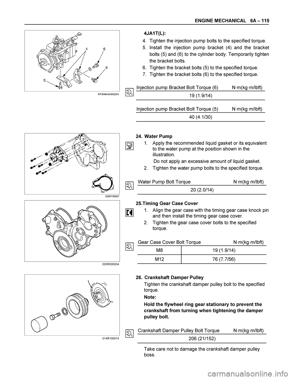
4JA1T(L):
4. Tighten the injection pump bolts to the specified torque.
5. Install the injection pump bracket (4) and the bracke
t
bolts (5) and (6) to the cylinder body. Temporarily tighten
the bracket bolts.
6. Tighten the bracket bolts (5) to the specified torque.
7. Tighten the bracket bolts (6) to the specified torque.
Injection pump Bracket Bolt Torque (6) N·m(kg·m/lbft)
19 (1.9/14)
Injection pump Bracket Bolt Torque (5) N·m(kg·m/lbft)
40 (4.1/30)
030RY00007
24. Water Pump
1. Apply the recommended liquid gasket or its equivalent
to the water pump at the position shown in the
illustration.
Do not apply an excessive amount of liquid gasket.
2. Tighten the water pump bolts to the specified torque.
Water Pump Bolt Torque N·m(kg·m/lbft)
20 (2.0/14)
25.Timing Gear Case Cover
1.
Align the gear case with the timing gear case knock pin
and then install the timing gear case cover.
2. Tighten the gear case cover bolts to the specified
torque.
Gear Case Cover Bolt Torque N·m(kg·m/lbft)
M8 19 (1.9/14)
M12 76 (7.7/56)
26. Crankshaft Damper Pulley
Tighten the crankshaft damper pulley bolt to the specified
torque.
Note:
Hold the flywheel ring gear stationary to prevent the
crankshaft from turning when tightening the damper
pulley bolt.
Crankshaft Damper Pulley Bolt Torque N·m(kg·m/lbft)
206 (21/152)
Take care not to damage the crankshaft damper pulley
boss.
014R100014 020R300004
Page 1256 of 4264
6A – 116 ENGINE MECHANICAL
27. Cylinder Head Gasket
The cylinder head gasket "TOP" mark must be facing up.
NOTE:
Before the gasket installation, measure the piston
head projection and select the appropriate head
gasket.
Refer to "INSPECTION AND REPAIR", "Cylinder Head
Gasket Selection".
28. Cylinder Head
1. Align the cylinder body dowels and the cylinder head
dowel holes.
Carefully place the cylinder head on the cylinder head
gasket.
2. Apply a coat of engine oil to the cylinder head bolt
threads and setting faces.
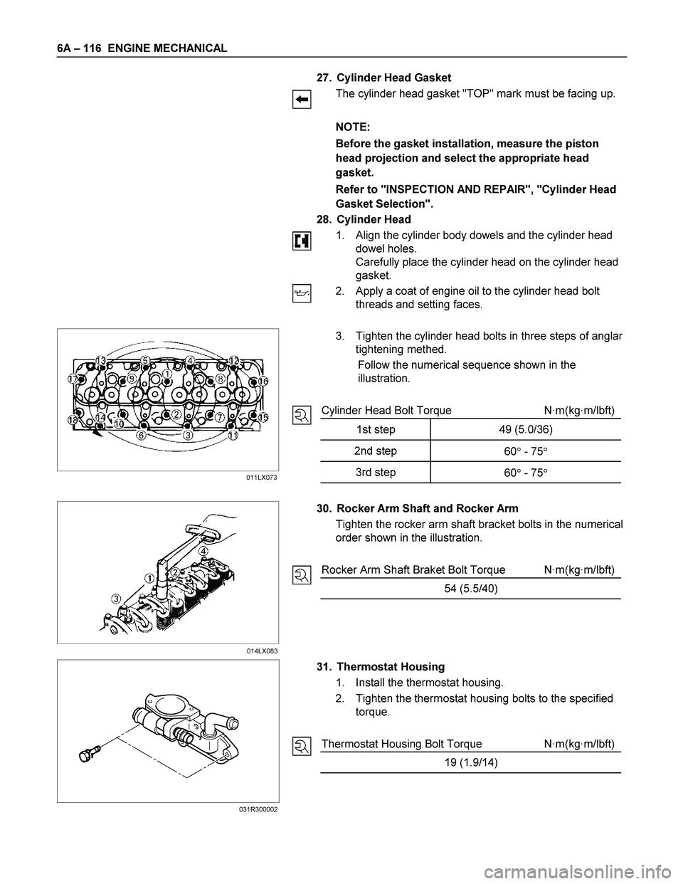
3. Tighten the cylinder head bolts in three steps of anglar
tightening methed.
Follow the numerical sequence shown in the
illustration.
Cylinder Head Bolt Torque N·m(kg·m/lbft)
1st step 49 (5.0/36)
2nd step
60� - 75�
3rd step
60� - 75�
30. Rocker Arm Shaft and Rocker Arm
Tighten the rocker arm shaft bracket bolts in the numerical
order shown in the illustration.
Rocker Arm Shaft Braket Bolt Torque N·m(kg·m/lbft)
54 (5.5/40)
31. Thermostat Housing
1. Install the thermostat housing.
2. Tighten the thermostat housing bolts to the specified
torque.
Thermostat Housing Bolt Torque N·m(kg·m/lbft)
19 (1.9/14)
014LX083 011LX073
031R300002
Page 1257 of 4264
ENGINE MECHANICAL 6A – 117
RTW46ASH001201
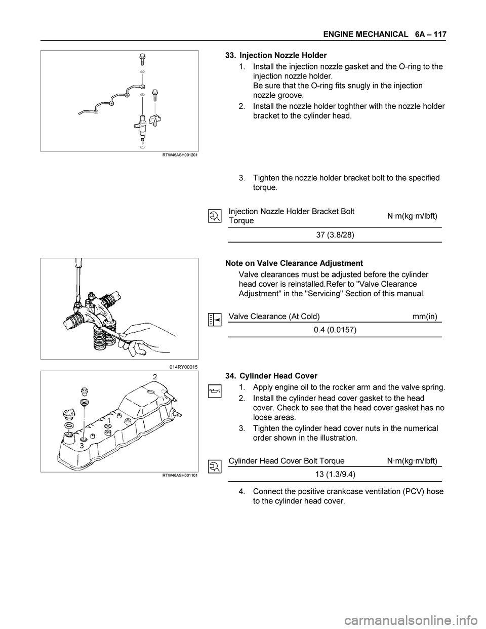
33. Injection Nozzle Holder
1. Install the injection nozzle gasket and the O-ring to the
injection nozzle holder.
Be sure that the O-ring fits snugly in the injection
nozzle groove.
2. Install the nozzle holder toghther with the nozzle holder
bracket to the cylinder head.
3. Tighten the nozzle holder bracket bolt to the specified
torque.
Injection Nozzle Holder Bracket Bolt
Torque N·m(kg·m/lbft)
37 (3.8/28)
Note on Valve Clearance Adjustment
Valve clearances must be adjusted before the cylinder
head cover is reinstalled.Refer to "Valve Clearance
Adjustment" in the "Servicing" Section of this manual.
Valve Clearance (At Cold) mm(in)
0.4 (0.0157)
RTW46ASH001101
34. Cylinder Head Cover
1. Apply engine oil to the rocker arm and the valve spring.
2. Install the cylinder head cover gasket to the head
cover. Check to see that the head cover gasket has no
loose areas.
3. Tighten the cylinder head cover nuts in the numerical
order shown in the illustration.
Cylinder Head Cover Bolt Torque N·m(kg·m/lbft)
13 (1.3/9.4)
4. Connect the positive crankcase ventilation (PCV) hose
to the cylinder head cover.
014RY00015
Page 1259 of 4264
ENGINE MECHANICAL 6A – 119
Installation
1. Exhaust Manifold
1) Install the exhaust manifold to the cylinder head with
the manifold gasket.
2) Tighten the exhaust manifold bolts and nuts to the
specified torque a little at a time.
Exhaust Manifold Bolt and Nuts
Torque N·m(kg·m/Ib ft)
27 (2.7/20)
3) Install the exhaust manifold bracket to the manifold
and the cylinder body.
Manifold Bracket Bolt Torque N·m(kg·m/Ib ft)
19 (1.9/14)
RTW46ASH001301
2. Oil Cooler with Oil Filter
1) Install the O-ring to the oil filter body flange groove.
2) Install the oil filter body to cylinder block and tighten to
the specified torque.
Oil Filter Body Bolt and Nut
Torque N·m(kg·m/Ib ft)
BOLT 19 (1.9/14)
NUT 24 (2.4/17)
3. Generator Bracket
Install the generator bracket to the cylinder body and
tighten the bracket bolts to the specified torque.
Bracket Bolt Torque N·m(kg·m/Ib ft)
40 (4.1/30)
027R100003
027R100004
066RY00001