Page 594 of 4264
10-86 CAB
REMOVAL AND INSTALLATION
(REAR SEAT BELT BACKLE)
RTW3A0SF000201
Removal Steps
� 1. Cover
2. Bolt
3. Rear seat belt buckle
Installation Steps
3. Rear seat belt buckle
� 2. Bolt
1. Cover
Important Operation - Removal
1. Cover
� Refer to Jump Seat (Extend Cab) in this section.
Important Operation - Installation
2. Bolt: Jump Seat Assembly/Rear Seat Belt Buckle to
Floor Panel
Torque N �
m (kgf �
m/lb �
ft)
40 (4.1 / 30)
Page 598 of 4264
 Removing the tailgate assembly may require")
10-90 CAB
Important Operations - Removal
2. Outside Handle Assembly
�
Disconnect the lock link and remove the 2 fixing bolts.
5. Tail Gate
1) Removing the tailgate assembly may require two people.
2) Remove the tailgate hinge fixing bolts.
Important Operations - Installation
7. Tail Gate Lock Striker
�
Tighten the lock striker fixing bolts to the specified
torque.
Torque N�m(kgf�m/lb�ft)
15 (1.5 / 11)
6. Tail Gate Hinge
�
Tighten the hinge fixing bolts to the specified torque.
C: Bolt
Torque N�m(kgf�m/lb�ft)
40 (4.1 / 30)
5. Tail Gate
1) A: Bolts
Torque N�
m(kgf�
m/lb�
in)
13 (1.3 / 113)
2) B: Bolt
Torque N�
m(kgf�
m/lb�
in)
25 (2.5 / 18)
3) Check the tailgate and rear body.
a. Clearance: 5.0 mm (0.20 in.)
b. Height (Step): Flush
c. Height (Step): Flush
3. Tail Gate Lock Assembly
�
Tighten the lock assembly fixing bolts to the specified
torque.
Torque N�
m(kgf�
m/lb�
ft)
15 (1.5 / 11)
2. Outside Handle Assembly
�
Tighten the outside handle assembly fixing bolts to the
specified torque and if remove the key cylinder (i
f
equipped) tighten it to the specified torque.
Torque N�
m(kgf�
m/lb�
in)
9 (0.9 / 78)
Page 603 of 4264

CLUTCH 7C-1
SECTION 7C
CLUTCH
TABLE OF CONTENTS
PAGE
Main Data and Specifications ......................................................................................... 7C- 2
General Description......................................................................................................... 7C- 3
Torque Specification ....................................................................................................... 7C-15
Servicing........................................................................................................................... 7C-19
Clutch................................................................................................................................ 7C-21
Removal and Installation ............................................................................................ 7C-21
Inspection and Repair................................................................................................. 7C-26
Clutch Control .................................................................................................................. 7C-32
Removal and Installation ............................................................................................ 7C-32
Master Cylinder ................................................................................................................ 7C-33
Disassembly ................................................................................................................ 7C-33
Reassembly ................................................................................................................. 7C-34
Slave Cylinder (4J, C24SE) ............................................................................................. 7C-35
Disassembly ................................................................................................................ 7C-35
Inspection and Repair................................................................................................. 7C-36
Reassembly ................................................................................................................. 7C-37
Slave Cylinder (6VE1) ...................................................................................................... 7C-38
Disassembly ................................................................................................................ 7C-38
Inspection and Repair................................................................................................. 7C-39
Reassembly ................................................................................................................. 7C-40
Hydraulic Damper Cylinder ............................................................................................. 7C-41
Inspection and Repair................................................................................................. 7C-41
Troubleshooting .............................................................................................................. 7C-42
Special Service Tool ........................................................................................................ 7C-51
Page 617 of 4264

Strength 4.")
CLUTCH 7C-15
TORQUE SPECIFICATION
STANDARD BOLTS
The torque values given in the following table should be applied where a particular torque is not specified.
N�
m (kgf�
m/lb ft)
Strength 4.8/4T 7T 8.8 9.8/9T
Class Refined Non-Refined
Bolt Identifi-
cation
Bolt
Diameter�
�� �
Pitch (mm)
-
M6 � 1.0 6 (0.6 / 52 lb.in) 7 (0.7 / 61 lb.in) 8 (0.8 / 69 lb.in) -
M8 � 1.25 13 (1.3 / 113 lb.in) 17 (1.7 / 12) 20 (2.0 / 14) 24 (2.4 / 17)
M10 � 1.25 27 (2.8 / 20) 37 (3.8 / 27) 42 (4.3 / 31) 50 (5.1 / 37)
M12 � 1.25 61 (6.3 / 45) 76 (7.8 / 56) 87 (8.9 / 64) 95 (9.7 / 70)
M14 �1.5 96 (9.8 / 71) 116 (11.8 / 85) 133 (13.6 / 98) 142 (14.5 / 105)
M16 � 1.5 130 (13.3 / 96) 170 (17.3 / 125) 193 (19.7 / 143) 200 (20.4 / 148)
M18 � 1.5 188 (19.2 / 139) 244 (24.9 / 180) 278 (28.3 / 205) 287 (29.3 / 212)
M20 � 1.5 258 (26.3 / 190) 337 (34.4 / 249) 385 (39.3 / 284) 396 (40.4 / 292)
M22 � 1.5 332 (33.9 / 245) 453 (46.3 / 335) 517 (52.7 / 381) 530 (54.1 / 391)
M24 � 2.0 449 (45.8 / 331) 570 (58.2 / 421) 651 (66.3 / 480) 692 (70.6 / 511)
* M10 � 1.5 26 (2.7 / 20) 36 (3.7 / 27) 41 (4.2 / 30) 48 (4.9 / 35)
* M12 � 1.75 57 (5.8 / 42) 71 (7.2 / 52) 80 (8.2 / 59) 89 (9.1 / 66)
* M14 � 2.0 89 (9.1 / 66) 110 (11.2 / 81) 125 (12.7 / 92) 133 (13.6 / 98)
* M16 � 2.0 124 (12.7 / 92) 162 (16.5 / 119) 185 (18.9 / 137) 191 (19.5 / 141)
Flange Bolt M6 � 1.0 7 (0.7 / 61 lb.in) 8 (0.8 / 69 lb.in) 9 (0.9 / 78 lb.in) -
M8
� 1.25 15 (1.5 / 11) 19 (1.9 / 14) 22 (2.2 / 16) 26 (2.7 / 20)
M10 � 1.25 31 (3.2 / 23) 41 (4.2 / 30) 47 (4.8 / 35) 56 (5.7 / 41)
M12 � 1.25 69 (7.0 / 51) 85 (8.7 / 63) 97 (9.9 / 72) 106 (10.8 / 78)
M14
� 1.5 104 (10.6 / 77) 126 (12.8 / 93) 144 (14.6 / 106) 154 (15.7 / 114)
M16 � 1.5 145 (14.8 / 127) 188 (19.2 / 139) 214 (21.8 / 158) 221 (22.5 / 163)
M18 � 1.5 - - - -
M20
� 1.5 - - - -
M22 � 1.5 - - - -
M24 � 2.0 - - - -
* M10
� 1.5 30 (3.1 / 22) 40 (4.1 / 30) 46 (4.7 / 34) 54 (5.5 / 40)
* M12 � 1.75 64 (6.5 / 47) 78 (8.0 / 58) 89 (9.1 / 66) 99 (10.1 / 73)
* M14 � 2.0 97 (9.9 / 72) 119 (12.1 / 88) 135 (13.8 / 99.7) 144 (14.7 / 107)
* M16
� 2.0 137 (14.0 / 101) 178 (18.2 / 132) 203 (20.7 / 132) 210 (21.5 / 155)
The asterisk * indicates that the bolts are used for female-threaded parts that are made of soft materials such as
casting, etc.
FLARE NUTS
Pipe diameter mm (in) Torque
N
�
�� �m (kgf
�
�� �m / lb ft) Pipe diameter mm (in) Torque N
�
�� �m (kgf
�
�� �m / lb ft)
4.76 (0.187) 16 (1.6 / 12) 10.00 (0.394) 54 (5.5 / 40)
6.35 (0.250) 26 (2.7 / 20) 12.00 (0.472) 88 (9.0 / 65)
8.00 (0.315) 44 (4.5 / 33) 15.00 (0.591) 106 (10.8 / 78)
Standard Hex.
Head Bolt
Page 618 of 4264
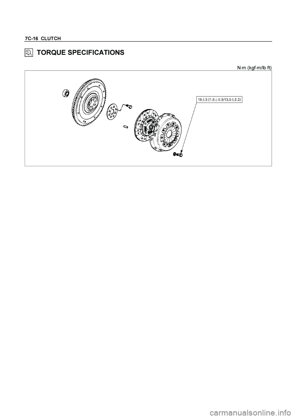
7C-16 CLUTCH
TORQUE SPECIFICATIONS
N�m (kgf�m/lb ft)
Page 625 of 4264
CLUTCH 7C-23
015RW053
6. Flywheel Assembly and Crank Bearing (6VE1)
(1) Remove flywheel assembly and crankshaft bearing. Do no
t
remove except for replacement.
(2) Use the remover 5-8840-2000-0 (J-5822) and sliding
hammer 5-8840-0019-0 (J-23907) to remove the crankshaf
t
bearing
Important Operations - Installation
Follow the removal procedure in reverse order to perform the
installation procedure.
Pay careful attention to the important points during the
installation procedure.
015RW054
6. Flywheel Assembly and Crank Bearing (6VE1)
(1) Install flywheel assembly and crankshaft bearing. Use the
installer 5-8840-0125-0 (J-26516-A) and driver handle 5-
8840-0007-0 (J-8092) to install the crankshaft bearing then
clean and lubricate with grease.
015RS047
(2) Install new flywheel fixing bolts in the order illustrated and
tighten them to the specified torque.
N�
m (kg�
m/lb ft)
6VE1 54 (5.5/40)
NOTE: Do not reuse the bolt and do not apply oil or thread lock
to the bolt.
Page 627 of 4264
CLUTCH 7C-25
(4) Clean the pressure plate surfaces.
(5) Align the pressure plate assembly
4 with the flywheel
knock pin
5.
(6) Install the pressure plate assembly to the flywheel.
(7) Tighten the clutch cover bolts a little at a time in the
numerical order shown in the illustration.
Clutch Cover Bolt Torque N�
m (kgf�
m/lb�
ft)
18 �
3 (1.8 �
0.3 / 13.0 �
2.2)
201RS017
(8) Remove the clutch pilot aligner.
Note:
Do not strike the clutch pilot aligner with a hammer to
remove it.
4JH1-TC, C24SE
6VE1
Page 765 of 4264
:
4JA1-TC / 4JH1-TC
Removal
1. Remove the passenger side front seat – refer to Section 10
CA")
ELECTRICAL-BODY AND CHASSIS 8A-107
REMOVAL AND INSTALLATION
ECM (ENGINE CONTROL MODULE):
4JA1-TC / 4JH1-TC
Removal
1. Remove the passenger side front seat – refer to Section 10
CAB.
2. Remove the passenger side front door opening scuff plate.
3. Raise the carpet to gain access to the four hex-head bolts
securing the ECM and ECM cover to the floorpan
.
4. Remove the four hex-head bolts.
5. Pull the two harness connector locks away from the
harness connectors and then remove the connectors form
the ECM.
6. Remove the ECM from the vehicle.
Refer to the Section 6E-ENGINE of this Manual.
IMPORTANT: The replacement ECM must be programmed.
“SPS (Service Programming System) and immobiliser
programming (if equipped) is/are necessary”
Installation
Follow the removal procedure in the reverse order to install the
ECM.
Torque passenger seat securing bolts to the specified value –
refer to Section 10 CAB
Pay close attention to the important points mentioned in the
following paragraphs.
Connector
Be absolutely sure that ECM is securely connected.
This will prevent a poor contact and open circuit.


(1) Remove flywheel assembly and crankshaft bearing. Do no
t
remove except for replacement.
(2) Use the remover 5-8840-2000-0")
 Clean the pressure plate surfaces.
(5) Align the pressure plate assembly
4 with the flywheel
knock pin
5.
(6) Install the pressure plate assembly to the flywheel.
(")