Page 496 of 4264

Adjust Nut
(2)
Clip
(3)
Bolt
(4)
Bolt
(5)
Parking Brake Cable T-end")
5D-6 PARKING BRAKE SYSTEM
This illustration is based on RHD model.
RTW35DMF000101
Legend
(1)
Adjust Nut
(2)
Clip
(3)
Bolt
(4)
Bolt
(5)
Parking Brake Cable T-end
(6)
Front Parking Brake Cable
Removal
1. Remove seat assembly and seat adjuster.
Refer to section 10.
2. Turn over the carpet so that front parking brake
cable (6) appears.
3. Remove adjust nut (1).
4. Pull out clip (2) and take out front parking brake
cable (6).
5. Remove bolt (3) (4).
6. Disconect parking brake cable T-ends (5) from
front parking brake cable (6).
7. Take out front parking brake cable through the
floor hole.
Installation
1. Apply grease (multipurpose type grease) to the
connecting portion of parking brake cable T-end
(5) and front parking brake equalizer. (arrow mark)
2. Let rear end (equalizer) of front parking brake
cable (6) enter the floor hole and connect it with
parking brake rear cable T-end (5).
3. Set front parking brake cable (6) in the parking
lever assembly.
4. Drive clip (2) into the outer cable groove of front
parking brake cable (6) at the outside of the
parking lever assembly.
5. Install bolt (3)(4) on the floor and tighten them to
the specified torque.
Torque: 15 N�
�� �m (1.5 kg�
�� �m/11 lb ft)
Page 498 of 4264

RTW35DSF000101
Legend
(1)
Rear Floor Console
(2)
Parking Brake Cable")
5D-8 PARKING BRAKE SYSTEM
Parking Brake Lever
Parking Brake Lever Assembly and Associated Parts (Bucket Seat)
RTW35DSF000101
Legend
(1)
Rear Floor Console
(2)
Parking Brake Cable T-end
(3)
Adjust Nut
(4)
Switch
(5)
Parking Brake Lever Assembly
(6)
Bolt
(7)
Equalizer
Removal
1. Remove rear floor console (1).
Refer to section 10.
2. Loosen adjust nut (3).
3. Remove bolt (6).
4. Remove switch (4).
5. Disconnect parking brake cable T-end (2) from
parking brake lever assembly (5).
6. Take out parking brake lever assembly (5).
Installation
1. Apply grease (multipurpose type grease) to the
connecting portion of parking brake rear cable T-
end (2) and parking brake lever equalizer (7).
(arrow mark)
2. Connect parking brake rear cable T-end (2) to
equalizer (7).
3. Install switch (4).
4. Tighten the parking brake lever fixing bolt (6) to
the specified torque.
Torque: 15 N�
�� �m (1.5 kg�
�� �m/11 lb ft)
5. Drive adjust nut (3) on parking brake assembly so
that parking brake cable T-end fits into equalize
r
(7).
6. Install rear floor console (1).
Refer to section 10.
7. Pull parking brake lever with a force equivalent to
operating force: 490 N (50 kg/110 lb), 10 times fo
r
conditioning.
8.
Adjust nut (3) so that parking brake lever goes
through 6�
8 notches, when pulled with a operation
force of 294 N (30 kg/66 lb).
9. Check brake for no drag.
Page 500 of 4264
 and shoe clamp spring (2).
4. Remove return spring (3).
5. Remove shoe assembll")
5D-10 PARKING BRAKE SYSTEM
Removal
1. Remove wheel and tire.
2. Remove brake drum.
3. Remove tension pin (1) and shoe clamp spring (2).
4. Remove return spring (3).
5. Remove shoe assemblly with parking brake leve
r
(4).
6. Remove shoe assembly with adjuster lever (5) and
spring (6).
7. Remove parking brake inner cable from parking
brake lever (4).
8. Use offset box wrench (12mm hex.) to compress
locking lugs on the cable, then remove parking
brake outer cable from back plate.
NOTE: Do not twist or bend the cable too much.
A damaged cable will cause poor operation or a cable
break down.
311RS012
Legend
(1) Offset Box Wrench (12mm hex)
9. Remove nut (8) to fix the cable (7) on the leaf
spring.
10. Take out parking brake rear cable (7) from the
back plate.
11. Remove bolt (9) and nut (10).
12. Disconnect T-end (11) from the equalizer of front
cable.
Installation
NOTE: Be sure to use the new shoe clamp spring (2)
and the new adjuster lever clip (14).
1. Apply grease (multipurpose type grease) to the
connecting portion of the rear cable (11) and
equalizer (13). (aroow mark).
2. Install parking brake outer cable in back plate and
inner cable in parking brake lever (4).
3. Install return spring (3).
4. Install shoe clamp spring (2) and tension pin (1)
5. Install shoe assembly with adjuster lever, shoe
assembly with parking brake lever (4) and spring
(6). ---- snap action
6. Install nut (8) and tighten it to the specified torque.
Torque: 7N�
�� �m (0.7 kg�
�� �m/61 lb in)
7. Connect T-end (11) with equalizer (13) through
outer cable retainer (12).
8. Install nut (10) and tighten it to the specifed
torque.
Torque: 15 N
�
�� �m (1.5 kg
�
�� �m/11 lb ft)
9. Install bolt (9) and tighten it to the specified
torque.
Torque: 7 N�
�� �m (0.7 kg�
�� �m/61 lb in)
10. Install brake drum.
11. Install wheel and tire.
12. Pull parking brake lever with a force equivalent to
poerating force: 490 N (50 kg/110 lb), 10 times fo
r
conditioning.
13. Adjust parking brake lever adjusting nut so that
parking brake lever goes through 8�
14 (bench
seat) or 6�
8 (bucket seat) notches, when pulled
with a operation force of 294N (30 kg/66 lb).
14. Check brake for no drag.
Page 503 of 4264
PARKING BRAKE SYSTEM 5D-13
Torque Specifications
N�
�� �m (kg�
�� �m/lb ft)
This illustration is based on RHD model.
RTW35DSF000201
N�
�� �m (kg�
�� �m/lb ft)
E05R300006
Page 514 of 4264
 Apply the window glass sealing adhesive
2.
If you are using an air gun, air pressure should be
maintained at 147 - 294 kpa.
After drying primer completely, apply a seali")
10-6 CAB
7) Apply the window glass sealing adhesive
2.
If you are using an air gun, air pressure should be
maintained at 147 - 294 kpa.
After drying primer completely, apply a sealing adhesive
(Sunstar #557 or equivalent) along the edge of the glass so
that the sealing adhesive has a 20 mm (0.79 in) junction a
t
middle of the vase of the glass.
Note :
Open time (1 min. or more) should be set after application
of the primer.
Bonding shall be done within 5 minutes after the sealing
adhesive has been applied.
8) Adjust the setting of the windshield glass with suction discs.
Set the windshield with sealing adhesive applied to entire
circumference in the body panel. Specifically, adjus
t
windshield support with the upper molding making contact
with the body panel, press the glass, and tighten the
windshield support.
9) Use unleaded gasoline and a soft cloth to wipe away any
excess adhesive.
Cure the bonding at a temperature of 68�
- 86�
F (20�
-
30�
C) for twenty-four hours.
Check that the windshield does not leak water.
8. Wiper Arm Assembly
�
Set the wiper arm/blade so that the tips of both blades
are positioned the specified value of
A and Bfrom the
upper edge of the cowl cover as shown in the figure.
A 40 mm (1.57 in)
B 52 mm (2.05 in)
�
Tighten the wiper arm assembly fixing nuts to the
specified torque.
Torque N�m (kgf�m/lb�ft)
31 (3.1/23)
Page 519 of 4264
CAB 10-11
2. Check Arm Screw
3. Lower Hinge Bolt
Position a wood block under the door for protection and
support the door assembly with hands at removal or
installation.
Important Operations – Installation
3. Lower Hinge Bolt; Hinge to Door
Torque N�
m (kgf�
m/lb�
ft)
34 (3.5/25)
2. Check Arm Screw; Check Arm to Body
Torque N�m (kgf�m/lb�ft)
24 (2.4/17)
Page 525 of 4264
CAB 10-17
Important Operations
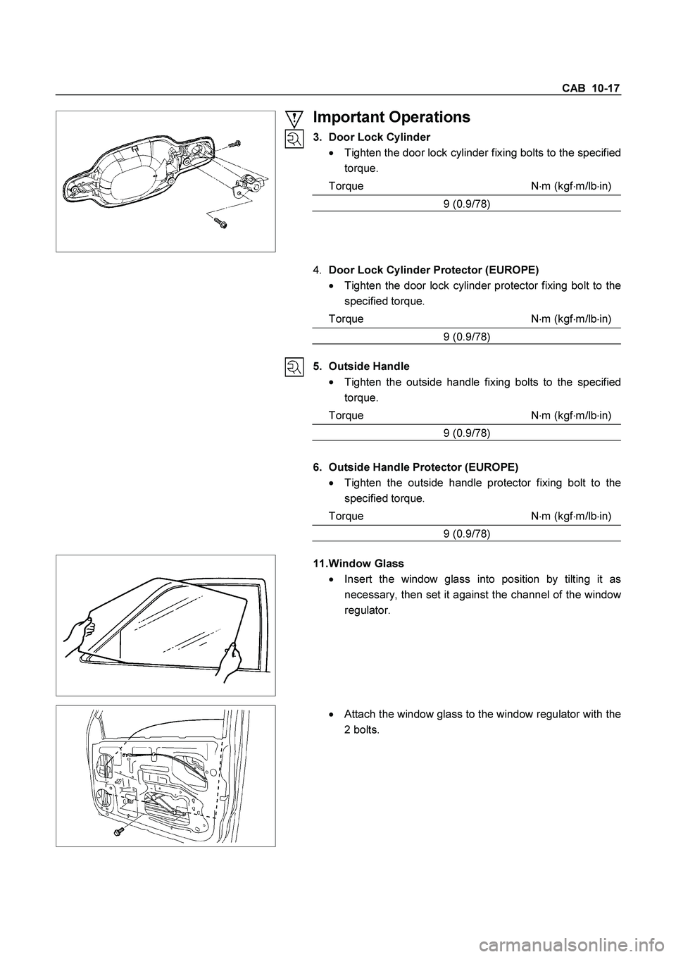
3. Door Lock Cylinder
�
Tighten the door lock cylinder fixing bolts to the specified
torque.
Torque N�
m (kgf�
m/lb�
in)
9 (0.9/78)
4. Door Lock Cylinder Protector (EUROPE)
�
Tighten the door lock cylinder protector fixing bolt to the
specified torque.
Torque N�m (kgf�m/lb�in)
9 (0.9/78)
5. Outside Handle
�
Tighten the outside handle fixing bolts to the specified
torque.
Torque N�
m (kgf�
m/lb�
in)
9 (0.9/78)
6. Outside Handle Protector (EUROPE)
� Tighten the outside handle protector fixing bolt to the
specified torque.
Torque N�
m (kgf�
m/lb�
in)
9 (0.9/78)
11. Window Glass
�
Insert the window glass into position by tilting it as
necessary, then set it against the channel of the windo
w
regulator.
�
Attach the window glass to the window regulator with the
2 bolts.
Page 529 of 4264
CAB 10-21
3. Lower Hinge Bolt
Position a wood block under the door for protection and
support the door assembly with hands at removal or
installation.
Important Operations – Installation
3. Lower Hinge Bolt; Hinge to Door
Torque N�
m (kgf�
m/lb�
ft)
34 (3.5/25)
2. Check Arm Screw; Check Arm to Body
Torque N�
m (kgf�
m/lb�
ft)
24 (2.4/17)