Page 425 of 4264
ANTI-LOCK BRAKE SYSTEM 5B-19
G-Sensor
G-Sensor and Associated Parts
RTW45BLF000101
Legend
1.
G-Sensor
2.
Nut
Removal
1. Remove the front floor console. (Refer to the section
Floor Console)
2. Disconnect the connector.
3. Remove the nuts.
4. Take out the G-sensor.
Installation
1. Set the G-sensor.
2. Install the nut and tighten it to specified torque.
Torque : 8.0 N·m (0.8 kg·m /69 lb in)
3. Connect the connector.
4.
Install the front floor console. (Refer to the
section Floor Console)
Page 427 of 4264

BRAKES 5C-1
SECTION 5C
BRAKES
TABLE OF CONTENTS
PAGE
General Description......................................................................................................... 5C- 2
Main Data and Specifications ......................................................................................... 5C- 9
Torque Specifications ..................................................................................................... 5C-10
Servicing........................................................................................................................... 5C-19
Front Brake Assembly ..................................................................................................... 5C-33
Removal and Installation ............................................................................................ 5C-33
Removal and installation of Disc Pad ....................................................................... 5C-37
Disassembly ................................................................................................................ 5C-39
Inspection and Repair................................................................................................. 5C-40
Reassembly ................................................................................................................. 5C-42
Rear Drum Brake Assembly ............................................................................................ 5C-44
Disassembly ................................................................................................................ 5C-44
Inspection and Repair................................................................................................. 5C-45
Reassembly ................................................................................................................. 5C-47
Brake Control ................................................................................................................... 5C-51
Removal and Installation ............................................................................................ 5C-51
Master Cylinder ................................................................................................................ 5C-52
Removal and Installation ............................................................................................ 5C-52
Disassembly ................................................................................................................ 5C-53
Inspection and Repair................................................................................................. 5C-55
Reassembly ................................................................................................................. 5C-56
Vacuum Booster .............................................................................................................. 5C-58
Removal and Installation ............................................................................................ 5C-58
Page 436 of 4264
5C-10 BRAKES
TORQUE SPECIFICATIONS
FRONT WHEEL BRAKE N�m(kgf�m/lb�ft)
E05R300016
Page 450 of 4264
 Rear wheel cylinder fluid pressure measurement
Step on the brake pedal until the fluid pressure of the
front wheel cylinder gets to 9.8Mpa (100kg/cm
2), and
c")
5C-24 BRAKES
RTW35CSH000201
3) Rear wheel cylinder fluid pressure measurement
Step on the brake pedal until the fluid pressure of the
front wheel cylinder gets to 9.8Mpa (100kg/cm
2), and
check the rear wheel cylinder fluid pressure. (Read the
value of the front wheel cylinder fluid pressure 2
seconds after the measurement. When measuring the
L.S.V fluid pressure, keep the brake pedal pressed
down without stepping it down twice or releasing it.)
Rear Wheel Cylinder Fluid Pressure MPa (kg/cm
2)
2WD 6.77�0.83 (69.0�8.5)
2WD (With High Ride
Suspension), 4WD 6.77�
0.83 (69.0�
8.5)
RTW35CSH000401
2. Oil Pressure Adjustment
1) LSPV spring length adjustment
Loosen the adjust nut of the LSPV spring joint, and
adjust the length of the LSPV spring.
When the oil pressure is insufficient, turn the adjust nu
t
clockwise to extend the span “A”. When the oil pressure
is too high, turn the adjust nut counterclockwise to
reduce the span “A”.
2) After adjustment, tighten the lock nut securely.
Lock Nut Torque N�m (kg�m/lb in)
11-20 (1.1-2.0/95-174)
Page 457 of 4264

BRAKES 5C-31
ADJUSTMENT PROCEDURE OF BRAKE PEDAL
The push rod serves as the brake pedal stopper when the
pedal is fully released.
Brake pedal height adjustment should be performed as follows.
RTW35CSH000601
Brake Pedal - Height
Measure the brake pedal height after making sure the pedal is
fully returned by the pedal return spring.
Note:
Pedal height (L2) must be measured after starting the
engine and increasing the revolution several times by
stepping on the accelerator pedal.
mm(in)
Pedal free play (L1) 6-10 (0.23 - 0.39)
M/T 174-186 (6.85-7.32)
RHD
LHD
A/T 176-188 (6.93-7.40) Height (L2)
Note:
Pedal free play must be measured after turning off the
engine and stepping on the brake pedal firmly five times
or more.
If the measured value deviates from the above range, adjust
the brake pedal as follows:
a) Disconnect the stop lamp switch.
b) Loosen the lock nut on the push rod.
c)
Adjust the brake pedal to the specified height by rotating the
push rod in the appropriate direction.
Lock Nut Torque N�
m(kgf�
m/lb�
�� �
ft)
12 - 18 (1.2 – 1.8 / 9 - 13)
d) Install the stop lamp switch.
Note:
Pedal height (L
2) must be 80 mm (3.14 in.) or more when
applying about 50 kg (110.25 lbs.) of stepping force.
331R300005
How to connect the CLEVICE of BOOSTER ROD with PEDAL
ARM. and how to adjust the PEDAL SW.
After connecting the CLEVIS of BOOSTER ROD with PEDAL
ARM, adjust the PEDAL SW mounted (PDA) to PEDAL
BRACKET by the procedure explained still more bellow.
1. Set the hole of the CLEVIS of BOOSTER&M/CYL ROD
with the hole of the PEDAL ARM.
2. Enter the PIN; PUSH ROD to PEDAL to these holes
from left side of the PEDAL.
3. Enter and fix the PIN; SANP PIN FIX to the DITCH o
f
the PIN; PUSH ROD to PEDAL from right side of the
PEDAL.
4. Release the LOCK by turning the SWITCH counter-
clock-wise.
Page 462 of 4264
5C-36 BRAKES
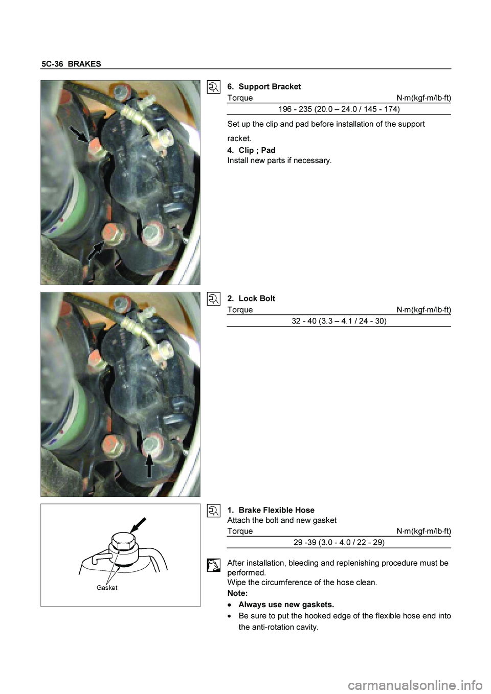
6. Support Bracket
Torque N�m(kgf�m/lb�ft)
196 - 235 (20.0 – 24.0 / 145 - 174)
Set up the clip and pad before installation of the support
racket.
4. Clip ; Pad
Install new parts if necessary.
2. Lock Bolt
Torque N�
m(kgf�
m/lb�
ft)
32 - 40 (3.3 – 4.1 / 24 - 30)
1. Brake Flexible Hose
Attach the bolt and new gasket
Torque N�m(kgf�m/lb�ft)
29 -39 (3.0 - 4.0 / 22 - 29)
After installation, bleeding and replenishing procedure must be
performed.
Wipe the circumference of the hose clean.
Note:
�
�� �
Always use new gaskets.
�
Be sure to put the hooked edge of the flexible hose end into
the anti-rotation cavity.
Page 464 of 4264
5C-38 BRAKES
3. Caliper Assembly
Lower the caliper into its original position.
Do not damage the flexible hose by twisting or pulling it.
4. Lock Bolt
Attach the lock bolt to the caliper.
Torque N�m(kgf�m/lb�ft)
32 - 40 (3.3 – 4.1 / 24 - 30)
Page 469 of 4264

BRAKES 5C-43
3. Dust seal ; Piston
Install the dust seal on the pistons.
4. Piston
Apply clean brake fluid to the piston, the dust seal is certainly
put into the slot on the piston and attach the caliper.
When inserting the piston into the cylinder, use finger pressure
only. Do not use a mallet or other impact tools, since damage
to the cylinder wall or ring seal can result.
The movement of a caliper piston into a caliper bore should be
smooth and even. If a caliper piston is frozen or difficult to
bottom, the caliper requires overhaul or replacement.
RTW35CSH000701
When not entering with a finger, insert a discarded inner brake
pad (2) or block of wood in front of the pistons. Using 2 large
C-clamps (1) installed over the body of the caliper (3) and
against the brake pad or block of wood, slowly bottom the
pistons evenly into the bores.
Insert the dust seal ring into the dust seal.
CAUTION:
Piston made by plastic material.
Don’t must be hit on the piston by hammer etc. and don’t
grasp to face of piston by pliers.
5. Bleeder
Torque N�m(kgf�m/Ib�in)
9 – 16 (0.9 – 1.6 / 78 - 139)
6. Cap