Page 206 of 4264
4B-42 REAR AXLE
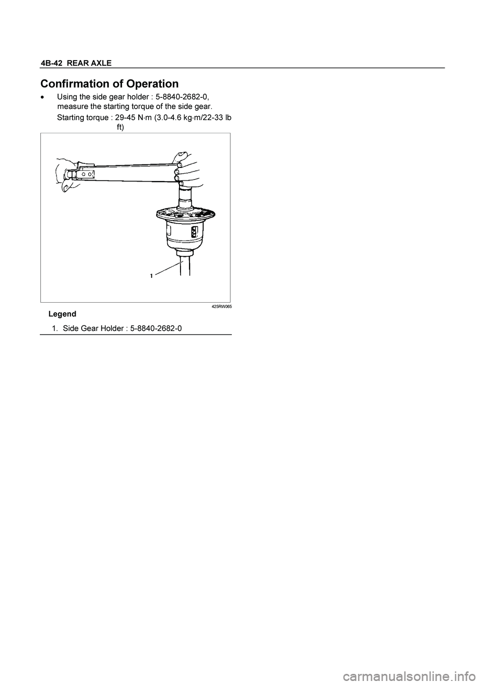
Confirmation of Operation
� Using the side gear holder : 5-8840-2682-0,
measure the starting torque of the side gear.
Starting torque : 29-45 N�m (3.0-4.6 kg�m/22-33 lb
ft)
425RW065
Legend
1.
Side Gear Holder : 5-8840-2682-0
Page 214 of 4264
4B-50 REAR AXLE
3. OIL LEAKAGE
1) Differential Carrier Leakage
Checkpoint Trouble Cause Countermeasure
Correct the oil levelToo much gear oil NG
Reapply the liquid gasket
and/or tighten the lock nut to
the specified torque
Reapply the liquid gasket
Tighten the bolts to the
specified torque
Replace the oil seal
Ring gear thrust boltLoose lock nut and/or liquid
Liquid gasket seal bed
Loose bolts
Oil sealWorn or defective oil seal
Differential carrier
Clean the air breatherAir breatherClogged air breather
NG NG NG NG NG
OK OK OK
OK
Gear oil level
Page 215 of 4264
REAR AXLE 4B-51
2) Axle Case Leakage
Checkpoint Trouble Cause Countermeasure
Tighten the drain plug and/or
replace the gasket(s)Loose drain plug and/or
defective gasket(s) NG
Reapply the liquid gasket
Tighten the bolts to the
specified torque
Clean the air breather
Liquid gasket seal bad
Loose bolts
Air breatherClogged air breather
Differential carrier
Replace the axle caseAxle caseCracked axle case
NG NG NG NG
OK OK
OK
Oil filler and drain plug
Page 226 of 4264

4C1-6 FRONT WHEEL DRIVE
RECOMMENDED LIQUID GASKET
Type Brand Name Manufacture Remarks
RTV*
Silicon Base ThreeBond 1207B
ThreeBond 1207C
ThreeBond 1215
Three Bond
Three Bond
Three Bond
For Engine Repairs
For Axle Case
Repairs, T/M
Water Base ThreeBond 1141E Three Bond For Engine Repairs
Solvent ThreeBond 1104
BelcoBond 4
BelcoBond 401
BelcoBond 402 Three bond
Isuzu
Isuzu
Isuzu
For Engine Repairs
Anerobic LOCTITE 515
LOCTITE 518 Loctite
Loctite All
* RTV : Room Temperature Vulcanizer
Note :
1. It is very important that the liquid gaskets listed above or their exact equivalent be used on the vehicle.
2. Be careful to use the specified amount of liquid gasket.
Follow the manufacture's instructions at all times.
3. Be absolutely sure to remove all lubricants and moisture from the connecting surfaces before applying
the liquid gasket.
The connecting surfaces must be perfectly dry.
4. LOCTITE 515 and LOCTITE 518 harden upon contact with a metal surface.
Do not apply LOCTITE 515 or LOCTITE 518 between two metal surfaces having a clearance of greater
than 0.25 mm (0.01 in). Poor adhesion will result.
RECOMMENDED THREAD LOCKING AGENTS
LOCTITE Type LOCTITE Color Application Steps
LOCTITE 242
Blue 1. Completely remove all lubricant and moisture from the bolts and
the female threaded surfaces of the parts to be joined.
The surfaces must be perfectly dry.
LOCTITE 262
Red 2. Apply LOCTITE to the bolts.
LOCTITE 270
Green
LOCTITE 271
Red
3. Tighten the bolts to the specified torque.
4. Wait at least on hour before continuing the installation procedure.
Page 236 of 4264

4C1-16 FRONT WHEEL DRIVE
17. Support the differential case by the jack.
18. Remove the front axle mounting bolts and nuts, lower the
jack slowly. Remove the left side drive shaft end from the
knuckle, then lower the axle assembly from the vehicle.
CAUTION :
1. During the work, be sure that the axle assembly is
supported securly.
2. Be careful not to damage the bellows of the power
steering unit by interference.
3. Be careful not to damage the breater pipe and breater
pip bracket of the shift on the fly by interference.
Installation
1. Support the differential case by the jack.
2. Jack up the front drive axle assembly, install the left side
drive shaft to the knuckle, then install the mount bolts and
nuts.
CAUTION :
1. Be careful not to damage the bellows of the power
steering unit by interference.
2. Be careful not to damage the breater pipe and breater
pip bracket of the shift on the fly by interference.
3. When installing the drive shaft to the knuckle, be
careful not to damage the oil seal inside of the knuckle.
RTW34CSH000101
3. Tighten the mounting bolts and nuts to the specified torque.
Torque : 169 N·m (17.2kg·m/124 lb ft)
4. Install the right side knuckle with lower control arm to the
upper control arm.
Refer to Knuckle in Suspension section.
CAUTION :
When insert the drive shaft to the knuckle, be careful not
to damage the oil seal inside of the knuckle.
5. Align the bolt hole of the lower control arm, install the bolts
and nuts.
Page 237 of 4264

FRONT WHEEL DRIVE 4C1-17
NOTE :
Adjust the buffer clearance before tighten the bolts and nuts of
the lower control arm.
6. Install the breather hose of the front axle.
7. Install the actuator connector of the shift on the fly. (With
shift on the fly)
8. Install the tie-rod end of the power steering unit to the
knuckle, tighten the nut to the specified torque.
Torque : 98 N·m (10.0kg·m/73 lb ft)
9. Install lower bolts and nuts of the shock absorber, tighten it
to the specified torque.
Torque : 93 N·m (9.5kg·m/69 lb ft)
10. Install lower nuts of the stabilizer link, tighten it to the
specified torque.
Torque : 50 N·m (5.1kg·m/37 lb ft)
11. Install the suspension crossmember.
12. Install the torsion bar.
Refer to Torsion Bar in Suspension section.
13. Install the front propeller shaft.
Refer to Front Propeller Shaft in this section.
14. Install the hub and disc assembly and adjust the bearing
preload.
Refer to Front Hub and Disc in this section.
15. Install the wheel speed sensor of the antilock brake
system.
16. Install the brake caliper. Tighten the bolt of the caliper
bracket to the specified torque.
Torque : 155 N·m (15.8kg·m/115 lb ft)
17. Install the stone guard.
18. Install the tire and wheel.
19. Lower the vehicle, adjust the trim height.
Refer to Trim Height Adjustment in Steering section.
20. Tighten the bolts and nuts of the lower control arm to the
specified torque.
Refer to Lower Control Arm in Suspension section.
Page 241 of 4264
FRONT WHEEL DRIVE 4C1-21
Bushing Replacement
� Remove the bushings using a remover 5-8840-2309-0 and
hammer.
�
By using installer and base 5-8840-2309-0, press fit the
bushings into the bracket.
Reassembly
1. Install DOJ case to bracket.
2. Install oil seal and fix snap ring.
Discard the used oil seal, snap ring and install a new one.
3. Install bearing and fix snap ring.
Discard the used snap ring and install a new one.
4. Install bracket to axle case. Tighten the bracket bolt to the
specified torque.
Torque : 116 N·m (11.8kg·m/85 lb ft)
5. Apply 135g of the specified grease in UJ.
6. Install dust seal for UJ.
Discard the used dust seal and install a new one.
Legend
1. Bellows
2. Shaft
7.
Apply a thin coat of grease to the shaft for smooth
installation then install bellows.
CAUTION :
During bellows assembly, be sure to insert both ends of
the bellows into the case and shaft grooves.
Page 249 of 4264

FRONT WHEEL DRIVE 4C1-29
INSPECTION AND REPAIR
Make all necessary adjustments, repairs, and part replacements if wear, damage, or other problems are discovered
during inspection.
� Ring gear, pinion gear
� Bearing
�
Side gear, pinion gear, cross pin
�
Differential cage, carrier
�
Thrust washer
�
Oil seal
Visual Check
Inspect the following parts for wear, damage, or other
abnormal conditions.
Ring Gear Replacement
(1) The ring gear should always be replaced with the drive
pinion as a set.
(2) When installing the ring gear, apply LOCTITE 271 o
r
equivalent to the threaded hole and bolt.
(3) Tighten the fixing bolts in a diagonal sequence as
illustrated.
(4) Discard used bolts and install new ones.
Bolt Torque N�m (kgf�m/lb�ft)
107.9 � 9.8 (11 � 1/79.6 � 7.2)
Clearance Between the Differential Pinion
and the Cross Pin
mm(in)
Standard Limit
0.05 - 0.10 (0.002 - 0.004) 0.2 (0.008)
Clearance Between the Side Gear and the
Differential Box
mm(in)
Standard Limit
0.03 - 0.10 (0.001 - 0.004) 0.15 (0.006)
 Differential Carrier Leakage
Checkpoint Trouble Cause Countermeasure
Correct the oil levelToo much gear oil NG
Reapply the liquid gasket
and/or tighten")
 Axle Case Leakage
Checkpoint Trouble Cause Countermeasure
Tighten the drain plug and/or
replace the gasket(s)Loose drain plug and/or
defective gasket(s) NG
Reapply the l")
