Page 137 of 4264

PROPELLER SHAFT 4A-1
SECTION 4A
PROPELLER SHAFT
TABLE OF CONTENTS
PAGE
Main Data and Specifications ........................................................................................... 4A- 3
Rear Propeller Shaft...................................................................................................... 4A- 3
Torque Specifications ....................................................................................................... 4A- 5
Front Propeller Shaft ................................................................................................... 4A- 6
Torque Specifications ....................................................................................................... 4A- 7
Rear Propeller Shaft .......................................................................................................... 4A- 8
General Description ...................................................................................................... 4A- 8
Removal and Installation .............................................................................................. 4A-11
Universal Joint Disassembly........................................................................................ 4A-12
Inspection and Repair .................................................................................................. 4A-14
Universal Joint Reassembly ........................................................................................ 4A-16
Rear Propeller Shaft Assembly ........................................................................................ 4A-17
Disassembly and Reassembly .................................................................................... 4A-18
Front Propeller Shaft ........................................................................................................ 4A-19
Removal and Installation .............................................................................................. 4A-19
Disassembly ................................................................................................................. 4A-21
Universal Joint Disassembly and Reassembly ......................................................... 4A-23
Reassembly .................................................................................................................. 4A-27
Page 138 of 4264
.
REFER TO THE SRS COMPONENT AND WIRING
LOCATION VIEW IN ORDER TO DETERMINE
WHETHER YOU ARE PE")
4A-2 PROPELLER SHAFT
Service Precaution
WARNING: THIS VEHICLE HAS A
SUPPLEMENTAL RESTRAINT SYSTEM (SRS).
REFER TO THE SRS COMPONENT AND WIRING
LOCATION VIEW IN ORDER TO DETERMINE
WHETHER YOU ARE PERFORMING SERVICE ON
OR NEAR THE SRS COMPONENTS OR THE SRS
WIRING. WHEN YOU ARE PEREFORMING
SERVICE ON OR NEAR THE SRS COMPONENTS
OR THE SRS WIRING, REFER TO THE SRS
SERVICE INFORMATION. FAILURE TO FOLLOW
WARNING COULD RESULT IN POSSIBLE AI
R
BAG DEPLOYMENT, PERSONAL INJURY, OR
OTHERWISE UNNEEDED SRS SYSTEM
REPAIRS. CAUTION : Always use the correct fastener in the
proper location. When you replace a fastener,
use ONLY the exact part number for that
application. ISUZU will call out those fasteners
that require a replacement after removal. ISUZU
will also call out the fasteners that require thread
lockers or thread sealant. UNLESS OTHERWISE
SPECIFIED, do not use supplemental coatings
(Paints, greases, or other corrosion inhibitors)
on threaded fasteners or fastener joint
interfaces. Generally, such coatings adversely
affect the fastener torque and the joint clamping
force, and may damage the fastener. When you
install fasteners, use the correct tightening
sequence and specifications. Following these
instructions can help you avoid damage to parts
and systems.
Page 141 of 4264
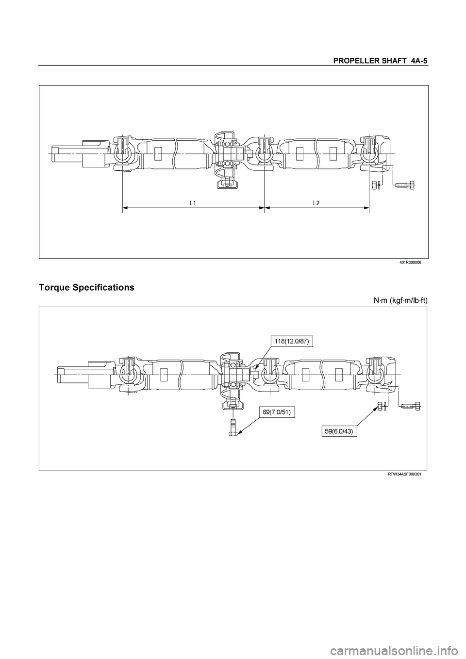
PROPELLER SHAFT 4A-5
401R300006
Torque Specifications
N�
m (kgf�
m/lb�
ft)
RTW34ASF000301
Page 143 of 4264
PROPELLER SHAFT 4A-7
Torque Specifications
RTW34ASF000201
Page 144 of 4264
4A-8 PROPELLER SHAFT
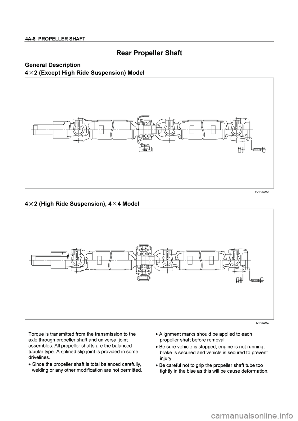
Rear Propeller Shaft
General Description
4�
�� �2 (Except High Ride Suspension) Model
F04R300001
4
�
�� �2 (High Ride Suspension), 4
�
�� �4 Model
401R300007
Torque is transmitted from the transmission to the
axle through propeller shaft and universal joint
assembles. All propeller shafts are the balanced
tubular type. A splined slip joint is provided in some
drivelines.
�
Since the propeller shaft is total balanced carefully,
welding or any other modification are not permitted. �
Alignment marks should be applied to each
propeller shaft before removal.
�
Be sure vehicle is stopped, engine is not running,
brake is secured and vehicle is secured to prevent
injury.
�
Be careful not to grip the propeller shaft tube too
tightly in the bise as this will be cause deformation.
Page 146 of 4264

4A-10 PROPELLER SHAFT
Diagnosis of Propeller Shaft and
Universal Joint
Condition Possible cause Correction
Rough surface on splined yoke;
burred nicked or worn. Replace the seal. Minor burrs can
be Smoothed by careful use of
crocus cloth or fine stone honing.
Replace the yoke if badly burred. Leak at the Front Slip Yoke (An
Occasional Drop of Lubricant
Leaking from the Splined Yoke is
Normal)
Defective transmission rear oil seal. Replace the transmission rear oil
seal and replenish the transmission
oil.
Worn universal joint bearings. Replace.
Improper lubrication. Lubricate as directed.
Universal Joint Noise.
Loose flange bolts. Tighten to specifications.
Loose bushing bolts on the rear
springs or upper and lower control
arms. Tighten the bolts to specified
torque. Ping, Snap, or Click in Drive Line
(Usually Heard on Initial Load after
the Transmission is in Forward or
Reverse Gear)
Loose or out-of-phase end yoke. Remove end yoke, turn 180
degrees from its original position,
lubricate the splines and reinstall.
Tighten the bolts and pinion nut to
specified torque.
Squeak Lack of lubricant. Lubricate joints and splines. Also
check for worn or brinelled parts.
Loose or missing bolts at the
flanges. Replace or tighten bolts to specified
torque.
Incorrectly set front joint angle. Install shim under the transmission
support mount to change the front
joint angle.
Shudder on Acceleration (Low
Speed)
Worn universal joint. Replace.
Incorrect shaft runout. Replace.
Shaft out of balance. Adjust.
Transmission rear housing bushing,
transfer case housing bushing worn.Replace.
Vibration
Yoke spline jammed. Replace.
Page 147 of 4264

PROPELLER SHAFT 4A-11
Removal and Installation
401RS023
Removal
1. Raise the vehicle on a hoist.
NOTE:
Apply alignment marks on the flange at the rear
propeller shaft both front and rear side.
2. Remove center bearing fixing bolt.
3. Remove rear axle side bolt, nut and washer.
4. Remove rear propeller shaft.
NOTE:
Plug the hole of the transmission rear end to prevent oil
leakage.
401L100007
Installation
NOTE:
Cover the slip yoke with cloth to avoid damage to the oil seal
contact surface, when removing propeller shaft from
transmission. Do not damage the oil seal contact surface of
slip yoke with other parts at removal and installation.
Completely remove the dust or foreign matter from the
connecting surface of flange coupling on each end of the
propeller shaft.
1.
Align the mark which is applied at removal and insert the
propeller shaft in the transmission.
2. Install rear propeller shaft and tighten the bolts to the
specified torque.
Torque: 63 N�
�� �m(6.4kg�
�� �m/46 lb�
�� �ft)
3. Install center bearing and tighten the bolts to the specified
torque.
Torque: 69 N
�
�� �m(7.0kg
�
�� �m/51 lb
�
�� �ft)
Page 154 of 4264
4A-18 PROPELLER SHAFT
Disassembly
1. Disassembly the three portions of the journal assemblies.
2. Remove the splined yoke, the 1st tube assembly with cente
r
bearing, the 2nd tube assembly and the flange yoke.
3. Remove the lock nut.
4. Remove the center yoke, the plain washer the cente
r
bearing and the 1st tube assembly.
Reassembly
1. Install the center bearing on the 1st tube assembly.
Clean the bearing fitting face.
Repack the grease.
Amount of grease
required g(oz) Approx. 12 (0.42)
2. Install the plain washer and the center yoke.
3. Install the lock nut and tighten it to the specified torque.
Lock nut Torque : 118 N�
�� �m (12.0kg�
�� �m/87lb�
�� �ft)
(1) Discard the flange nut and install a new one.
(2) Stake the outer face of the flange nut against the slot in the
shaft.
4. Install the splined yoke, the 1st tube assembly with cente
r
bearing, the 2nd tube assembly and the flange yoke by
assembling the universal joint.