Page 1260 of 4264
6A – 120 ENGINE MECHANICAL
4. Water Inlet Pipe
1) Tighten the water inlet pipe bolts to the specified
torque.
Suction Pipe Bolt Torque N·m(kg·m/Ib ft)
19 (1.9/14)
5. Generator and Adjusting Plate
1) Install the generator to the bracket (1).
2) Temporarily tighten the generator bolt (2) and
adjusting plate bolts (3).
The bolts will be finally tightened after installation of
the cooling fan drive belt.
3) Connect the vacuum pump rubber hose (4) to the
vacuum pump (5), and the oil pan (6).
6. Vacuum Pump Oil Return Hose
Connect the vacuum oil pipe (7) to the vacuum pump, and
the cylinder body
052R300001
7. Compressor Bracket
1) Install the compressor bracket to the cylinder head.
2) Tighten the bracket bolts to the specified torque.
Bracket Bolt Torque N·m(kg·m/Ib ft)
M8�1.25
19 (1.9/14)
M10�1.25
40 (4.1/30)
066RY00002 032R300001
042RY00003
Page 1261 of 4264

ENGINE MECHANICAL 6A – 121
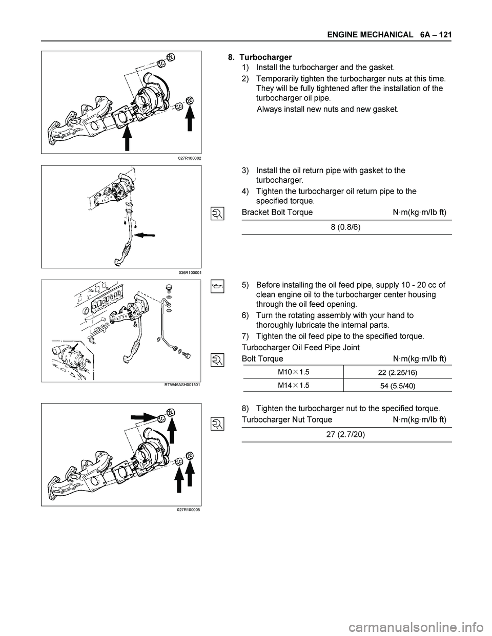
8. Turbocharger
1) Install the turbocharger and the gasket.
2) Temporarily tighten the turbocharger nuts at this time.
They will be fully tightened after the installation of the
turbocharger oil pipe.
Always install new nuts and new gasket.
3) Install the oil return pipe with gasket to the
turbocharger.
4) Tighten the turbocharger oil return pipe to the
specified torque.
Bracket Bolt Torque N·m(kg·m/Ib ft)
8 (0.8/6)
5) Before installing the oil feed pipe, supply 10 - 20 cc of
clean engine oil to the turbocharger center housing
through the oil feed opening.
6) Turn the rotating assembly with your hand to
thoroughly lubricate the internal parts.
7) Tighten the oil feed pipe to the specified torque.
Turbocharger Oil Feed Pipe Joint
Bolt Torque N·m(kg·m/Ib ft)
M10�1.5
22 (2.25/16)
M14�1.5
54 (5.5/40)
RTW46ASH001501
8) Tighten the turbocharger nut to the specified torque.
Turbocharger Nut Torque N·m(kg·m/Ib ft)
27 (2.7/20)
036R100001
027R100005027R100002
Page 1262 of 4264

6A – 122 ENGINE MECHANICAL
RTW46ASH001601
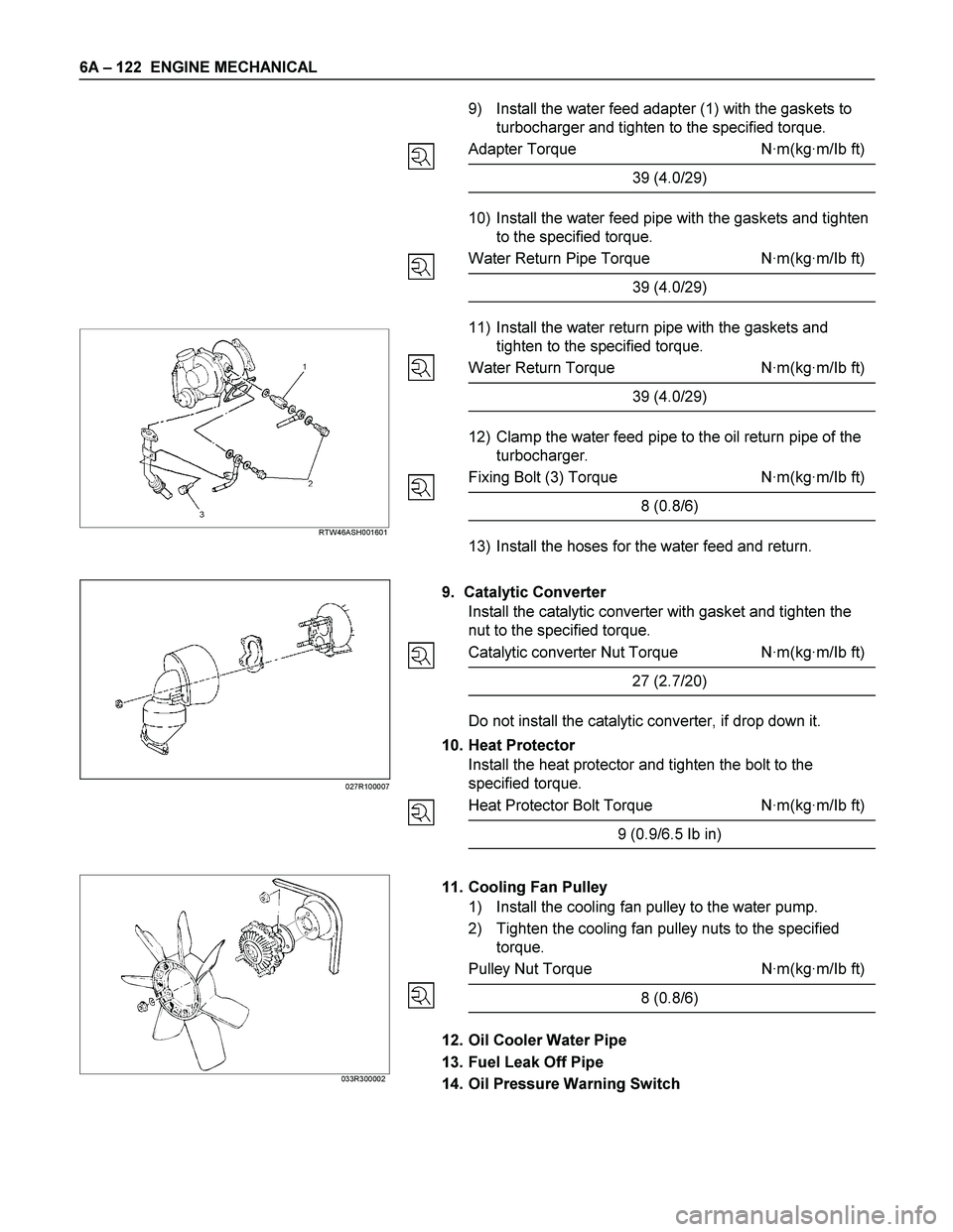
9) Install the water feed adapter (1) with the gaskets to
turbocharger and tighten to the specified torque.
Adapter Torque N·m(kg·m/Ib ft)
39 (4.0/29)
10) Install the water feed pipe with the gaskets and tighten
to the specified torque.
Water Return Pipe Torque N·m(kg·m/Ib ft)
39 (4.0/29)
11) Install the water return pipe with the gaskets and
tighten to the specified torque.
Water Return Torque N·m(kg·m/Ib ft)
39 (4.0/29)
12) Clamp the water feed pipe to the oil return pipe of the
turbocharger.
Fixing Bolt (3) Torque N·m(kg·m/Ib ft)
8 (0.8/6)
13) Install the hoses for the water feed and return.
9. Catalytic Converter
Install the catalytic converter with gasket and tighten the
nut to the specified torque.
Catalytic converter Nut Torque N·m(kg·m/Ib ft)
27 (2.7/20)
Do not install the catalytic converter, if drop down it.
10. Heat Protector
Install the heat protector and tighten the bolt to the
specified torque.
Heat Protector Bolt Torque N·m(kg·m/Ib ft)
9 (0.9/6.5 Ib in)
033R300002
11. Cooling Fan Pulley
1) Install the cooling fan pulley to the water pump.
2) Tighten the cooling fan pulley nuts to the specified
torque.
Pulley Nut Torque N·m(kg·m/Ib ft)
8 (0.8/6)
12. Oil Cooler Water Pipe
13. Fuel Leak Off Pipe
14. Oil Pressure Warning Switch
027R100007
Page 1263 of 4264

ENGINE MECHANICAL 6A – 123
15. Starter Motor
Tighten the starter motor bolts to the specified torque.
Starter Motor Bolt Torque N·m(kg·m/Ib ft)
85 (8.7/63)
16. Injection Pump
17. Injection Pump Cover (4JA1TC/4JH1TC only)
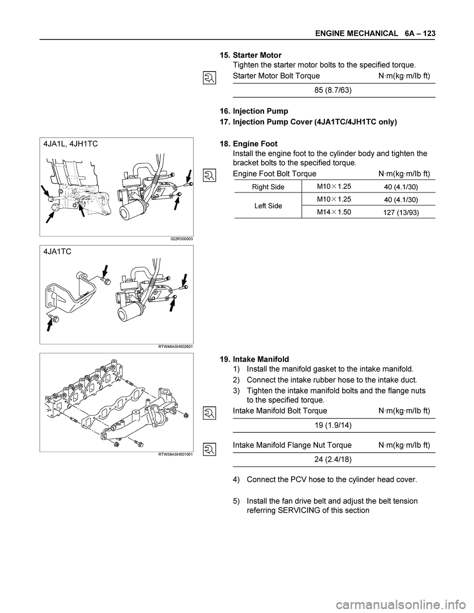
18. Engine Foot
Install the engine foot to the cylinder body and tighten the
bracket bolts to the specified torque.
Engine Foot Bolt Torque N·m(kg·m/Ib ft)
Right Side M10�1.25
40 (4.1/30)
M10�1.25
40 (4.1/30) Left Side
M14�1.50
127 (13/93)
4JA1L, 4JH1TC
022R300003
4JA1TC
RTW46ASH002601
RTW36ASH001001
19. Intake Manifold
1) Install the manifold gasket to the intake manifold.
2) Connect the intake rubber hose to the intake duct.
3) Tighten the intake manifold bolts and the flange nuts
to the specified torque.
Intake Manifold Bolt Torque N·m(kg·m/Ib ft)
19 (1.9/14)
Intake Manifold Flange Nut Torque N·m(kg·m/Ib ft)
24 (2.4/18)
4) Connect the PCV hose to the cylinder head cover.
5) Install the fan drive belt and adjust the belt tension
referring SERVICING of this section
Page 1264 of 4264

6A – 124 ENGINE MECHANICAL
20. Power Steering Oil Pump Bracket
Oil Pump Braket Nut and Bolt Torque N·m(kg·m/Ib ft)
1M10�1.25
37 (3.8/28)
2
3M8�1.25
18 (1.8/13) (Bolt ID:8)
040R300005
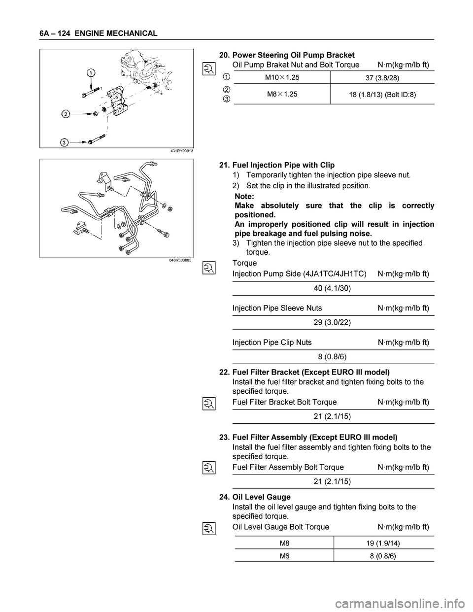
21. Fuel Injection Pipe with Clip
1) Temporarily tighten the injection pipe sleeve nut.
2) Set the clip in the illustrated position.
Note:
Make absolutely sure that the clip is correctly
positioned.
An improperly positioned clip will result in injection
pipe breakage and fuel pulsing noise.
3) Tighten the injection pipe sleeve nut to the specified
torque.
Torque
Injection Pump Side (4JA1TC/4JH1TC) N·m(kg·m/Ib ft)
40 (4.1/30)
Injection Pipe Sleeve Nuts N·m(kg·m/Ib ft)
29 (3.0/22)
Injection Pipe Clip Nuts N·m(kg·m/Ib ft)
8 (0.8/6)
22. Fuel Filter Bracket (Except EURO III model)
Install the fuel filter bracket and tighten fixing bolts to the
specified torque.
Fuel Filter Bracket Bolt Torque N·m(kg·m/Ib ft)
21 (2.1/15)
23. Fuel Filter Assembly (Except EURO III model)
Install the fuel filter assembly and tighten fixing bolts to the
specified torque.
Fuel Filter Assembly Bolt Torque N·m(kg·m/Ib ft)
21 (2.1/15)
24. Oil Level Gauge
Install the oil level gauge and tighten fixing bolts to the
specified torque.
Oil Level Gauge Bolt Torque N·m(kg·m/Ib ft)
M8 19 (1.9/14)
M6 8 (0.8/6)
431RY00013
Page 1265 of 4264
ENGINE MECHANICAL 6A – 125
25. EGR Valve
Install the EGR valve assembly to the intake minifold with
the two gasket.
Tighten the four nuts to the specified torque.
Nut Tolque N·m(kg·m/Ib ft)
31 (3.1/23)
Connector the vacuum hose.
025R100008
RTW36ASH000301
26-1. EGR Pipe
Install the EGR valve adapter with the gasket to the EGR
valve assembly and install the EGR pipe with the gasket.
Tighten fixing bolts and nuts to the specified torque.
EGR Valve Adapter Bolts N·m(kg·m/Ib ft)
24 (2.4/17)
EGR Pipe Bolts and Nuts N·m(kg·m/Ib ft)
27 (2.7/20)
RTW48ASH001801
26-2. EGR Cooler (EURO III model only)
27. Intake Pipe and Throttle Body (4JA1TC/4JH1TC only)
Install the throttle body with the gasket to the intake
manifold and install the intake duct with the gasket.
Tighten the two bolts and the two nuts to the specified
torque.
Throttle Body and Intake Duct N·m(kg·m/Ib ft)
Bolt 19 (1.9/14)
Nut 24 (2.4/17)
RTW36ASH000201
28. Clutch Assembly or Flex Plate
Page 1270 of 4264
6A – 130 ENGINE MECHANICAL
REASSEMBLY
Reassembly Steps
1.
Oil pump body 5.
Pinion gear
2.
Drive gear 6. Strainer
3. Driven gear 7. Relief valve assembly
4. Pump cover 8.
Oil pipe
Reassembly procedure is shown in the illustration above numerical order.
Pump cover fixing bolts torque: 16 N·m (1.6 kg·m/12 lb ft)
051R100006
Page 1274 of 4264
6A – 134 ENGINE MECHANICAL
RTW46ASH001701
1. Body
2. Oil Filter Safety Valve
3. Oil Cooler Safety Valve
Tighten the oil filter
A and oil cooler B relief valve to the
specified torque.
Regulating Valve N·m(kg·m/lb ft)
A 64 (6.5/48)
4. Oil Cooler
5. Gasket
6. Bolt
Tighten bolt with gasket and oil cooler to the specified
torque.
Bolt Torque N·m(kg·m/lb ft)
40 (4.1/30)
7. Oil Filter Cartridge
1) Apply engine oil to the O-ring.
2) Tighten the oil filter cartridge to the specified torque.
Filter wrench: 5-8840-0201-0
Oil Filter Cartride Torque N·m(kg·m/lb ft)
18 (1.8/13)
050R300006
050RY00004