Page 1291 of 4264

ENGINE COOLING 6B – 11
Inspection and Repair
The water pump is not disassembled type.
Make necessary parts replacement if extreme wear or
damage is found during inspection. Should any of the
following problems occur, the entire water pump assembly
must be replaced.
��Cracks in the water pump body
��Coolant leakage from the seal unit
��Excessive radial play or abnormal noise in the fan center
when rotate by hand
��Excessive thrust play in the fan center (Standard play: less
than 0.2mm)
��Cracks or corrosion in the impeller
Installation
1. Water Pump
1) Install the water pump with new gasket.
2) Tighten bolts and nuts to specified torque.
Water Pump Bolt/Nut Torque N·m(kg·m/lb ft)
20 (2.0/14)
2. Fan Drive Belt and Pulley
1) Install the fan drive belt and fan pulley.
2) Apply tension to the fan drive belt by moving the
generator.
3) Apply a force of 98N(10kg/22 lb) to the drive belt mid-
portion to check the drive belt deflection.
Fan Drive Belt Deflection mm (in)
New belt: 4-7(0.16-0.28)
Reuse belt: 6-9(0.24-0.35)
030R300002
030R300001
3. Fan and Fan Clutch
1) Install the fan and fan clutch to pulley.
2) Tighten the nuts to specified torque.
Fan Clutch Nut Torque N·m(kg·m/lb in)
8(0.8/69)
4. Upper Fan Shroud
Page 1292 of 4264
6B – 12 ENGINE COOLING
031R300003
5. Thermostat
Install the thermostat to the thermostat housing.
6. Water Outlet Pipe
1) Install the water outlet pipe with new gasket to the thermostat housing.
2) Tighten the outlet pipe bolt to specified torque.
Outlet Pipe Bolt Torque N ·m(kg ·m/lb ft)
19(1.9/14)
3) Connect the turbocharger-cooling pipe to outlet pipe.
7. Radiator Upper Hose
1) Connect the radiator upper hose to the water outlet pipe.
2) The knob of clamp shall be dircted to holizonal side.
3) Replenish the engine coolant.
Page 1294 of 4264
6B – 14 ENGINE COOLING
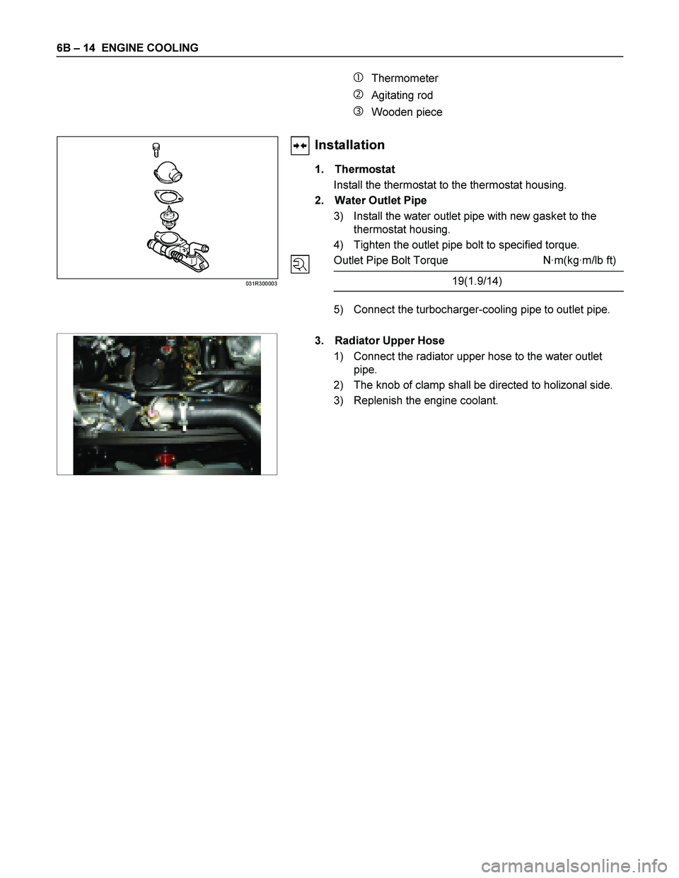
� Thermometer
� Agitating rod
� Wooden piece
Installation
1. Thermostat
Install the thermostat to the thermostat housing.
2. Water Outlet Pipe
3) Install the water outlet pipe with new gasket to the thermostat housing.
4) Tighten the outlet pipe bolt to specified torque.
Outlet Pipe Bolt Torque N ·m(kg ·m/lb ft)
19(1.9/14)
5) Connect the turbocharger-cooling pipe to outlet pipe.
031R300003
3. Radiator Upper Hose
1) Connect the radiator upper hose to the water outlet pipe.
2) The knob of clamp shall be directed to holizonal side.
3) Replenish the engine coolant.
Page 1300 of 4264

6B – 20 ENGINE COOLING
FAN CLUTCH WITH COOLING FAN
INSPECTION AND REPAIR
Make necessary correction or parts replacement if wear, damage or any other abnormal condition are found through
inspection.
033R300001
Visually inspect for damage, leak (sillicon grease) or other
abnormal conditions.
1. Inspection (on-vehicle)
1) Turn the fan clutch by hand when in a low temperature
condition before starting the engine, and confirm that it
can be turned readily.
2) Start the engine to warm it up until the temperature at
the fan clutch portion gets to around 80�C. Then stop
the engine and confirm that the fan clutch can be
turned with considerable effort (clutch torque) when
turned by hand.
If the fan clutch rotates more readily, however, this
indicates that the silicone grease is leaking internally.
Replace the fan clutch with a new one.
033RY00011
2. Inspection (in unit)
Warm up the bimetal of the fan clutch by using the heat
gun until the temperature gets to about 80�C when
measured with the thermistor. Then confirm that the fan
clutch can be turned with considerable effort (clutch
torque).
If the fan clutch retates more readily at this time, this
indicates that the silicone grease is leaking internally.
Replace the fan clutch with a new one.
Page 1310 of 4264

6C – 10 FUEL SYSTEM
Removal
CAUTION: When repair to the fuel system has been
completed, start engine and check the fuel system for
loose connection or leakage. For the fuel system
diagnosis, see Section “Driveability and Emission".
1. Disconnect battery ground cable.
2. Loosen slowly the fuel filler cap.
NOTE: Be careful not to spouting out fuel because of change
the pressure in the fuel tank.
NOTE: Cover opening of the filler neck to prevent any dus
t
entering.
3. Jack up the vehicle.
4. Support underneath of the fuel tank with a lifter.
5. Remove the inner liner of the wheel house at rear left side.
6. Remove fixing bolt of the filler neck from the body.
7.
Disconnect the quick connector (3) of the fuel tube from the
fuel pipe.
NOTE: Cover the quick connector to prevent any dust entering
and fuel leakage.
NOTE: Refer to“Fuel Tube/Quick Connector Fittings” in this
section when performing any repairs.
8. Remove fixing bolt (1) of the tank band and remove the
tank band (2).
9.
Disconnect the pump and sender connector on the fuel
pump and remove the harness from weld clip on the fuel
tank.
10.
Lower the fuel tank (5).
NOTE: When lower the fuel tank from the vehicle, don’t scratch
each hose and tube by around other parts.
Installation
1. Raise the fuel tank.
NOTE: When raise the fuel tank to the vehicle, don’t scratch
each hose and tube by around other parts.
2. Connect the pump and sender connector to the fuel pump
and install the harness to weld clip on the tank.
NOTE: The connector must be certainly connected agains
t
stopper.
3. Install the tank band and fasten bolt.
Torque N·m (kg·m / lb ft)
68 (6.9 / 50)
NOTE: The anchor of the tank band must be certainly installed
to guide hole on frame.
4. Connect the quick connector of the fuel tube to the fuel pipe
and the evapo tube from evapo joint connector.
NOTE: Pull off the left checker on the fuel pipe.
NOTE: Refer to “Fuel Tube/Quick Connector Fittings” in this
section when performing any repairs.
Page 1317 of 4264

FUEL SYSTEM 6C – 17
FILLER NECK
Removal
1.
Remove the fuel tank.
NOTE: Refer to "Fuel Tank" in this section.
2.
Put a marking the following point as the filler neck assembl
y
is restored.
�
Each joint area of the hose (to restore axial direction and
insertion length of the hose)
�
Each fasten area of the clamp (to restore axial direction
and position of the clamp)
�
Each bolt in the clamp (to restore fasten length of bolt in
the clamp)
�
The band clip (to restore position and fasten length o
f
the band clip)
NOTE: Cover end of each hose and pipe to prevent any dust
entering.
Installation
1.
Align each marking and restore the following point.
�
Each joint area of the hose (Restore axial direction and
insertion length of the hose)
�
Each fasten area of the clamp (Restore axial direction
and position of the clamp)
�
Each bolt in the clamp (Restore fasten length of bolt in
the clamp)
Torque N·m (kg·m / lb ft)
2.5 (0.25 / 21.7)
filler neck side except flat deck model.
�
The band clip (Restore position and fasten length of the
band clip)
2.
Install the fuel tank.
NOTE: Refer to "Fuel Tank" in this section.
Page 1322 of 4264
6C – 22 FUEL SYSTEM
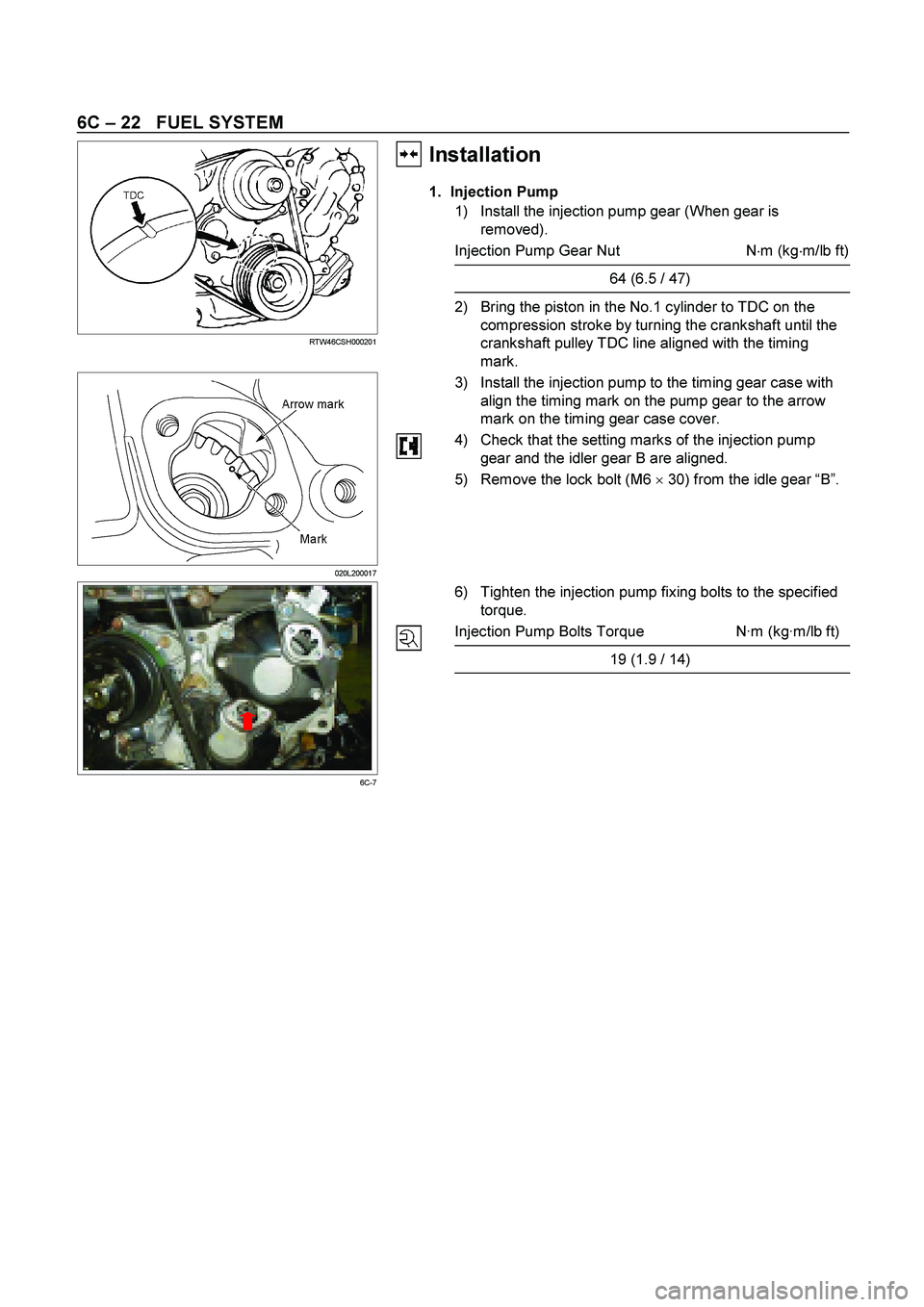
RTW46CSH000201
Installation��
1. Injection Pump
1) Install the injection pump gear (When gear is
removed).
Injection Pump Gear Nut N�
m (kg�
m/lb ft)
64 (6.5 / 47)
2) Bring the piston in the No.1 cylinder to TDC on the
compression stroke by turning the crankshaft until the
crankshaft pulley TDC line aligned with the timing
mark.
020L200017
3) Install the injection pump to the timing gear case with
align the timing mark on the pump gear to the arrow
mark on the timing gear case cover.
4) Check that the setting marks of the injection pump
gear and the idler gear B are aligned.
5) Remove the lock bolt (M6 �
30) from the idle gear “B”.
6C-7
6) Tighten the injection pump fixing bolts to the specified
torque.
Injection Pump Bolts Torque N·m (kg·m/lb ft)
19 (1.9 / 14)
Page 1323 of 4264

RTW46CSH000101
4JA1TC/4JH1TC
RTW36AMH000101
2. Injection Pump Bracket
1) Install the injection pump")
FUEL SYSTEM 6C – 23
4JA1T (L)
RTW46CSH000101
4JA1TC/4JH1TC
RTW36AMH000101
2. Injection Pump Bracket
1) Install the injection pump bracket (6) and the bracket
bolts (7) and (8) to the cylinder body. Temporarily
tighten the bracket bolts.
2) Tighten the bracket bolts (7) to the specified torque.
3) Tighten the bracket bolts (8) to the specified torque.
Note:
Tighten the bracket bolt (8) first.
Injection Pump Bracket Torque N·m(kg·m / lb ft)
(8) 19 (1.9 / 14)
(7) 40 (4.1 / 30)
3. Timing Check Hole Cover
Install the timing check hole cover and tighten bolts to the
specified torque.
Timing Check Hole Cover Bolts
Torque N·m(kg·m / lb ft)
8 (0.8 / 69)
4. Injection Pump Cover (4JA1TC/4JH1TC only)
5. Intake Manifold
1) Install the intake manifold with gasket.
Intake Manifold Bolts
Torque N·m(kg·m / lb ft)
19 (1.9 / 14)
Intake Manifold Nuts Torque N·m(kg·m / lb ft)
24 (2.4 / 17)
2) Install the EGR valve to the intake manifold and EGR
pipe temporarily.
3) Tighten the nuts and bolts to the specified torque
Torque N�m (kg�m/lb ft)
Nuts 24 (2.4/17)
Bolts 27 (2.8/20)
 Install the water outlet pipe with new gasket to the")