Page 1359 of 4264

ENGINE ELECTRICAL 6D – 21
RTW06DSH000201
9. Through Bolt
1. Place a pilot bar into the through bolt hole to align the
front cover and the rear cover.
2. Install the through bolts and tighten them to the
specified torque.
Through Bolt Torque N�m (kg�m/lb�ft)
3.1 � 3.9 (0.32 � 0.41 / 2.6 � 3.5)
11. Vaccum Pump
To install the generator -
1. Note the direction of the arrow on the vacuum pump.
2. Look forward from the base of the arrow to locate the
3 generator fixing points.
3. Twist the fixing points down and to the left to align
them with the middle of the center plate and the rotor.
RTW46DSH006101
Install vanes into slits in rotor.
The vanes should be installed with the chamfered side
facing outward.
RTW46DSH002401
Install the vacuum pump housing.
Make sure that the O-ring is not projecting beyond the
slots of the center plate.
Take care so that no scratching takes place on the vane
resulted by contact with the housing.
RTW46DSH002501
Install the housing in the generator and fix it with the three
bolts.
Supply engine oil (5cc or so) from the oil port and check
that the generator pulley can be turned smoothly with your
hand.
Generator Housing Bolt Torque N�m (kg�m/lb�ft)
5.9 � 6.9 (0.6 � 0.7 / 5.2 � 6.1)
Page 1360 of 4264

6D – 22 ENGINE ELECTRICAL
STARTER MOTOR
REMOVAL AND INSTALLATION
Read this Section carefully before performing any removal and installation procedure. This Section gives you
important points as well as the order of operation. Be sure that you understand everything in this Section before you
begin.
Important Operations - Removal
Starter Motor
1. Disconnect the battery cable and the ground cable at the battery terminals.
2. Disconnect the magnetic switch cable at the terminal bolts.
3. Disconnect the battery cable at the starter motor and the ground cable at the cylinder body.
4. Remove the starter motor from the engine.
Important Operations – Installation
Follow the removal procedure in the reverse order to
perform the installation procedure. Pay careful attention to
the important points during the installation procedure.
Starter Motor
1. Install the starter motor to the rear plate.
2. Tighten the starter motor bolts to the specified torque.
Starter Motor Bolt Torque N �m (kg �m/lb �ft)
85 (8.7/63)
3. Reconnect the battery cable at the starter motor and
the ground cable at the cylinder body.
4. Reconnect the battery cable and the ground cable at the battery terminals.
Page 1368 of 4264
6D – 30 ENGINE ELECTRICAL
RTW46DSH005601
Important Operations
1. Magnetic Switch Assembly
1. Attach the torsion spring to the hole in the magnetic
switch as illustrated.
2. Insert the shift lever into the plunger hole of the
magnetic switch.
RTW46DSH005701
7. Gear Case
3,8. Dust Cover
1. Install the magnetic switch assembly in the gear case.
2. Install the dust cover.
Dust Cover Bolt Torque N�m (kg�m/lb�ft)
8 (0.8/5.4)
10. Pinion Assembly
Apply a coat of grease to the reduction gear and install the
pinion assembly to the armature shaft.
065RY00041
RTW46DSH004501
21. Brush Holders
1. Install the brushes into the brush holder with raising
the spring end of the brush spring.
Take care not to damage the commutator face.
2. Install the brush holder with aligning the peripheries of
the yoke and the brush holder.
Page 1369 of 4264
ENGINE ELECTRICAL 6D – 31
24. Through Bolt
Install the through bolts in the rear cover and tighten them
to the specified torque.
Through Bolt Torque N�m (kg�m/lb�ft)
8.1 (0.83/6.00)
065RY00044
RTW46DSH002601
25. Lead Wire
Connect the lead wire in the magnetic switch and tighten
the terminal nut to the specified torque.
Lead Wire Terminal Nut Torque N�m (kg�m/lb�ft)
8.6 (0.88/6.40)
RTW46DSH005801
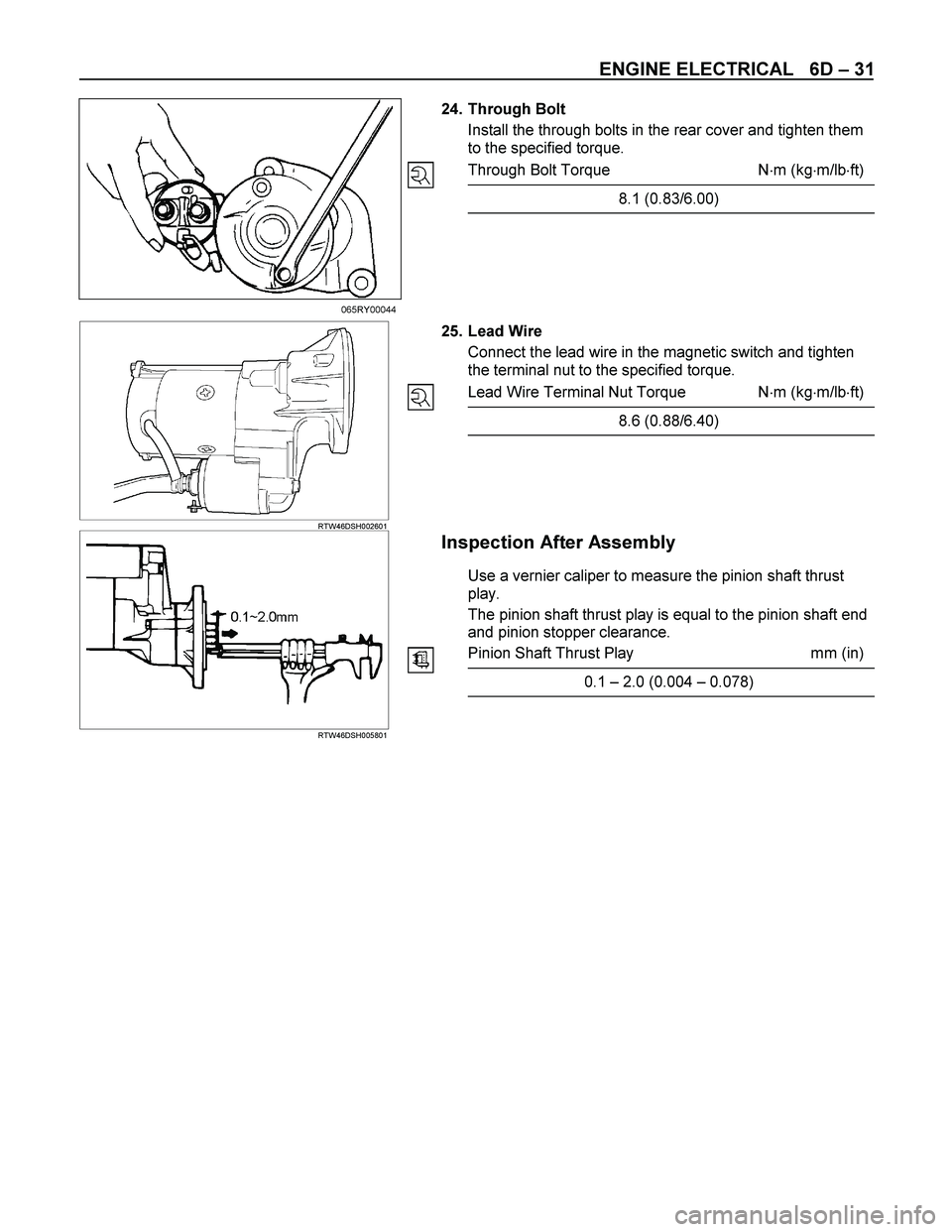
Inspection After Assembly
Use a vernier caliper to measure the pinion shaft thrust
play.
The pinion shaft thrust play is equal to the pinion shaft end
and pinion stopper clearance.
Pinion Shaft Thrust Play mm (in)
0.1 – 2.0 (0.004 – 0.078)
Page 1755 of 4264

4JA1/4JH1 ENGINE DRIVEABILITY AND EMISSIONS 6E–383
HESITATION, SAG, STUMBLE SYMPTOM
DEFINITIONS: Momentary lack of response as the
accelerator is pushed down. Can occur at any vehicle
speed. Usually most pronounced when first trying to
make the vehicle move, as from a stop sign. May cause
the engine to stall if severe enough.
time rpm
Sug
Hesitation Stumble
Step Action Value(s) Yes No
1Was the “On-Board Diagnostic (OBD) System Check”
performed?
—Go to Step 2Go to On Board
Diagnostic
(OBD) System
Check
2 1. Perform a bulletin search.
2. If a bulletin that addresses the symptom is found,
correct the condition as instructed in the bulletin.
Was a bulletin found that addresses the symptom?—Verify repair Go to Step 3
3 Was a visually/physical check performed?
—Go to Step 4Go to Visual /
physical Check
4 Is the customer using the incorrect fuel type? Diesel fuel
onlyReplace with
diesel fuel Go to Step 5
5 Check the torque converter clutch (TCC) for proper
operation (if A/T model). If a problem is found, repair
as necessary.
Was a problem found?—Verify repair Go to Step 6
6 Visually/physically inspect for the following conditions.
Restrict air intake system. Check for a restricted air
filter element, or foreign objects blocking the air
intake system
Check for objects blocking or ex cessive deposits in
the throttle bore and on the throttle plate
Check for a condition that causes a large vacuum
leak, such as an incorrectly installed or faulty
crankcase ventilation hose.
Restrict air intake system at the turbocharger.
Check for objects blocking the turbocharger
compressor wheel or turbine shaft sticking.
If a problem is found, repair as necessary.
Was a problem found?—Verify repair Go to Step 7
7 Check the ECM & PSG grounds to verify that they are
clean and tight. Refer to the ECM wiring diagrams.
Was a problem found?—Verify repair Go to Step 8
Page 1774 of 4264

6E–402 4JA1/4JH1 ENGINE DRIVEABILITY AND EMISSIONS
POOR FUEL ECONOMY SYMPTOM
DEFINITIONS: Fuel economy, as measured by an actual road test, is noticeably lower than expected. Also, economy
is noticeably lower than it was on this vehicle at one time, as previously shown by an actual road test. (Larger than
standard tires will cause odometer readings to be incorrect, and that may cause fuel economy to appear poor when it
is actually normal.)
Step Action Value(s) Yes No
1Was the “On-Board Diagnostic (OBD) System Check”
performed?
—Go to Step 2Go to On Board
Diagnostic
(OBD) System
Check
2 1. Perform a bulletin search.
2. If a bulletin that addresses the symptom is found,
correct the condition as instructed in the bulletin.
Was a bulletin found that addresses the symptom?—Verify repair Go to Step 3
3 Was a visually/physical check performed?
—Go to Step 4Go to Visual /
physical Check
4 Check owner's driving habits.
Is the A/C “On” full time?
Are tires at the correct pressure?
Are ex cessively heavy loads being carried?
Is acceleration too much, too often?—Go to Step 5Go to Step 6
5 Review the items in Step 4 with the customer and
advise as necessary.
Is the action complete?—System OK—
6 Check for low engine coolant level.
Was a problem found? —Verify repair Go to Step 7
7 Check for incorrect or faulty engine thermostat. Refer
to Engine Cooling.
Was a problem found?—Verify repair Go to Step 8
8 Check for proper calibration of the speedometer.
Does the speed indicated on the speed meter closely
match the vehicle speed displayed on the Tech 2?—Go to Step 10Go to Step 9
9 Diagnose and repair the inaccurate speedometer
condition as necessary. Refer to Vehicle Speed
Sensor in Electrical Diagnosis.—Veri fy repai r—
10 Check for proper calibration of the fuel gauge.
Was a problem found? —Verify repair Go to Step 11
11 Check the torque converter clutch (TCC) for proper
operation (if A/T model). If a problem is found, repair
as necessary.
Was a problem found?—Verify repair Go to Step 12
12 1. Using the Tech 2, ignition “On” and engine “Off”.
2. Monitor the “Neutral Switch” in the data display.
Does the Tech 2 indicate correct “Neutral Switch”
status depending on any shift positions?
If a problem is found, repair as necessary.
Was the problem found?—Verify repair Go to Step 13
Page 1790 of 4264

Location
Under the left-hand side seat.
Removal Procedure
1. Disconnect the negativ")
6E–418 4JA1/4JH1 ENGINE DRIVEABILITY AND EMISSIONS
ON-VEHICLE SERVICE PROCEDURE
ENGINE CONTROL MODULE
(ECM)
Location
Under the left-hand side seat.
Removal Procedure
1. Disconnect the negative battery cable.
2. Remove the seat left-hand side.
3. Roll up the floor carpet.
4. Remove four bolts from the ECM cover.
5. Disconnect the two connectors from the ECM.
Installation Procedure
1. Connect the two connectors to the ECM.
2. Put on the ECM to the floor panel.
3. Tighten the ECM cover by four bolts with specifiedtightening torque.
Tightening torque
Bolts: 8.0 - 12.0 N·m (0.8 - 1.2 kgf·m)
4. Lay the floor carpet ex actly.
5. Put on the seat to the floor panel and tighten with
specified tightening torque.
Tightening torque
Bolts: 40.0 N·m (4.1 kgf·m)
6. Connect the negative battery cable.
NOTE: The replacement ECM must be programmed.
Refer to section of the Service Programming System
(SPS) in this manual.
Following ECM programming, the immobilizer system (if
equipped) must be linked to the ECM. Refer to section
11 “Immobilizer System-ECM replacement” for the
ECM/Immobilizer linking procedure.
Page 1791 of 4264

SENSOR
Location
Installed to the clutch housing.
Removal Procedure
1. Disconnect the negative battery cable.
2. Disconne")
4JA1/4JH1 ENGINE DRIVEABILITY AND EMISSIONS 6E–419
CRANKSHAFT POSITION (CKP)
SENSOR
Location
Installed to the clutch housing.
Removal Procedure
1. Disconnect the negative battery cable.
2. Disconnect connector from the CKP sensor.
3. Loosen a bolt and remove the CKP sensor from the
clutch housing.
Installation Procedure
1. Install the CKP sensor to the clutch housing.
2. Tighten CKP sensor by a bolt with specified
tightening torque.
Tightening Torque
Bolts: 8.0 - 12.0 N·m (0.8 - 1.2 kgf·m)
3. Connect a CKP sensor connector to the CKP
sensor.
4. Connect the negative battery cable.
NOTE: Verify any DTCs (diagnosis Trouble Code) are
not stored after replacement.
ENGINE COOLANT TEMPERATURE
(ECT) SENSOR
Location
Installed to the thermostat housing.
Removal Procedure
1. Disconnect the negative battery cable.
2. Drain enough engine coolant so that the coolant
level will be below the ECT sensor.
3. Disconnect connector from the ECT sensor.
4. Loosen and remove the ECT sensor from the
thermostat housing.
NOTE: Cool down the engine before above procedures
are carried out.
Installation Procedure
1. Apply sealer to threads of screw at the ECT sensor.
2. Tighten the ECT sensor with specified tightening
torque.
Tightening Torque
Bolt: 13N·m (1.3kgf·m)
3. Connect a ECT sensor connector to the ECT
sensor.
4. Fill the engine coolant.
5. Connect the negative battery cable.
NOTE: Verify any DTCs (diagnosis Trouble Code) are
not stored after replacement.
Verify no engine coolant leaking from the sensor
threads after replacement.