Page 1799 of 4264
EXHAUST SYSTEM 6F – 5
Important Operations – Installation
Follow the removal procedure in the reverse order to
perform the installation procedure. Pay careful attention to
the important points during the installation procedure.
1. Front Pipe Nut
Connect the exhaust pipe to the catalytic converter.
Torque N�m (kg�m/lb�ft)
67 (6.8/49)
2. Middle pipe Nut (4�
�� �4 only)
Connect the middle pipe to the front pipe.
Torque N�m (kg�m/lb�ft)
43 (4.4/32)
3. Silencer Front Nut
Connect the silencer to the front or middle pipe.
Torque N�m (kg�m/lb�ft)
43 (4.4/32)
Page 1808 of 4264
6F – 14 EXHAUST SYSTEM
Installation
1. EGR Cooler Adapter
2. Gasket
3. EGR Cooler Assembly
4. Bolt
Tighten the bolts to the specified torque.
EGR adapter bolt torque N�m(kg�m/lb ft)
27(2.8/20)
5. Gasket
6. EGR Pipe Assembly
7. Bolt
Tighten bolts temporarily.
8. Bolt
Tighten bolts temporarily.
9. Gasket
10. Bolt
Tighten bolts temporarily.
11.Gasket
12.Bolt
Tighten bolts temporarily.
Finally tighten all bolts to the specified torque.
Confirm that there is no misalignment on the sealing
surface.
Bolt torque (Cooler-pipe) N�m(kg�m/lb ft)
27(2.8/20)
Bolt torque (Cooler-bracket) N�m (kg�m/lb ft)
24(2.4/17)
Bolt torque (Adapter-EGR valve) N�m (kg�m/lb ft)
27(2.8/20)
Bolt torque (Pipe-manifold) N�m (kg�m/lb ft)
27(2.8/20)
Page 1826 of 4264

Crankshaft............................................................... 6A-71
Crankshaft and Associated Parts..................... 6A-71
Disassembly...........")
6A-2 ENGINE MECHANICAL (6VE1 3.5L)
Crankshaft............................................................... 6A-71
Crankshaft and Associated Parts..................... 6A-71
Disassembly........................................................ 6A-71
Inspection and Repair........................................ 6A-73
Reassembly......................................................... 6A-75
Piston and Connecting Rod.................................. 6A-79
Piston, Connecting Rod and Associate
Parts.................................................................... 6A-79
Disassembly........................................................ 6A-79
Inspection and Repair........................................ 6A-80
Reassembly......................................................... 6A-84
Cylinder Block......................................................... 6A-87
Cylinder Block and Associated Parts............... 6A-87
Disassembly........................................................ 6A-88
Inspection and Repair........................................ 6A-88
Reassembly......................................................... 6A-89
Main Data and Specification................................. 6A-93
Special Tool......................................................... 6A-99
Service Precaution
WARNING: THIS VEHICLE HAS A SUPPLEMENTAL
RESTRAINT SYSTEM (SRS). REFER TO THE SRS
COMPONENT AND WIRING LOCATION VIEW IN
ORDER TO DETERMINE WHETHER YOU ARE
PERFORMING SERVICE ON OR NEAR THE SRS
COMPONENTS OR THE SRS WIRING. WHEN YOU
ARE PERFORMING SERVICE ON OR NEAR THE
SRS COMPONENTS OR THE SRS WIRING, REFE
R
TO THE SRS SERVICE INFORMATION. FAILURE TO
FOLLOW WARNINGS COULD RESULT IN
POSSIBLE AIR BAG DEPLOYMENT, PERSONAL
INJURY, OR OTHERWISE UNNEEDED SRS SYSTEM
REPAIRS.
CAUTION: Always use the correct fastener in the
proper location. When you replace a fastener, use
ONLY the exact part number for that application.
ISUZU will call out those fasteners that require a
replacement after removal. ISUZU will also call out
the fasteners that require thread lockers or thread
sealant. UNLESS OTHERWISE SPECIFIED, do not
use supplemental coatings (Paints, greases, o
r
other corrosion inhibitors) on threaded fasteners o
r
fastener joint interfaces. Generally, such coatings
adversely affect the fastener torque and the joint
clamping force, and may damage the fastener.
When you install fasteners, use the correct
tightening sequence and specifications. Following
these instructions can help you avoid damage to
parts and systems.
Page 1829 of 4264
 6A-5
3. Trouble In Fuel System
Symptom Possible Cause Action
Starting motor turns over and spark
occurs but engine does not start. Fuel tank empty Fill
Water in f")
ENGINE MECHANICAL (6VE1 3.5L) 6A-5
3. Trouble In Fuel System
Symptom Possible Cause Action
Starting motor turns over and spark
occurs but engine does not start. Fuel tank empty Fill
Water in fuel system Clean
Fuel filter clogged Replace filter
Fuel pipe clogged Clean or replace
Fuel pump defective Replace
Fuel pump circuit open Correct or replace
Evaporative Emission Control System
circuit clogged Correct or replace
Multiport Fuel Injection System faultyRefer to “Electronic Fuel Injection"
section
4. Engine Lacks Compression
Symptom Possible Cause Action
Engine lacks compression Spark plug loosely fitted Tighten to specified torque
Valve timing incorrect Adjust
Cylinder head gasket defective Replace gasket
Valve incorrectly seated Lap valve
Valve stem seized Replace valve and valve guide
Valve spring weakened or broken Replace
Cylinder or piston rings worn Overhaul engine
Piston ring seized Overhaul engine.
Engine Compression Test Procedure
1. Start and run the engine until the engine reaches
normal operating temperature.
2. Turn the engine off.
3. Remove all the spark plugs.
4. Remove ignition coil fuse (15A) and disable the
ignition system.
5. Remove the fuel pump relay from the relay and
fuse box.
6. Engage the starter and check that the cranking
speed is approximately 300 rpm.
7. Install cylinder compression gauge into spark plug
hole.
8. With the throttle valve opened fully, keep the
starter engaged until the compression gage needle
reaches the maximum level. Note the reading.
9. Repeat the test with each cylinder.
If the compression pressure obtained falls belo
w
the limit, engine overhaul is necessary.
Limit; 1000 kPa (145 psi)
Page 1845 of 4264
 6A-21
Cylinder Head Cover LH
Removal
1. Disconnect battery ground cable.
2. Disconnect positive crankcase ventilation hose.
3. Remove camshaft angle sensor connecto")
ENGINE MECHANICAL (6VE1 3.5L) 6A-21
Cylinder Head Cover LH
Removal
1. Disconnect battery ground cable.
2. Disconnect positive crankcase ventilation hose.
3. Remove camshaft angle sensor connector.
4. Remove ground cable fixing bolt on cylinder head
cover.
5. Ignition coil connector and ignition coil.
� Disconnect the three connectors from the
ignition coils.
� Remove harness bracket bolt on cylinder head
cover.
� Remove fixing bolts on ignition coils.
060RW078
Legend
(1) Ignition Coil Connector
(2) Bolt
(3) Ignition Coil Assemblies
6. Remove fixing bolt for fuel injector harness
bracket.
7. Remove eight fixing bolts, then the cylinder head
cover.
010RW001
Installation
1. Install cylinder head cover.
� Clean the sealing surface of cylinder head and
cylinder head cover to remove oil and sealing
materials completely.
� Apply sealant (TB-1207B or equivalent) of bead
diameter 2-3 mm at eight place of arched area
of camshaft bracket on front and rear sides.
� The cylinder head cover must be installed with
in 5 minutes after sealant application to preven
t
hardening of sealant.
� Tighten bolts to the specified torque.
Torque : 9 N�
�� �m (0.9 kg�
�� �m/7 lb ft)
010RW006
Page 1846 of 4264
6A-22 ENGINE MECHANICAL (6VE1 3.5L)
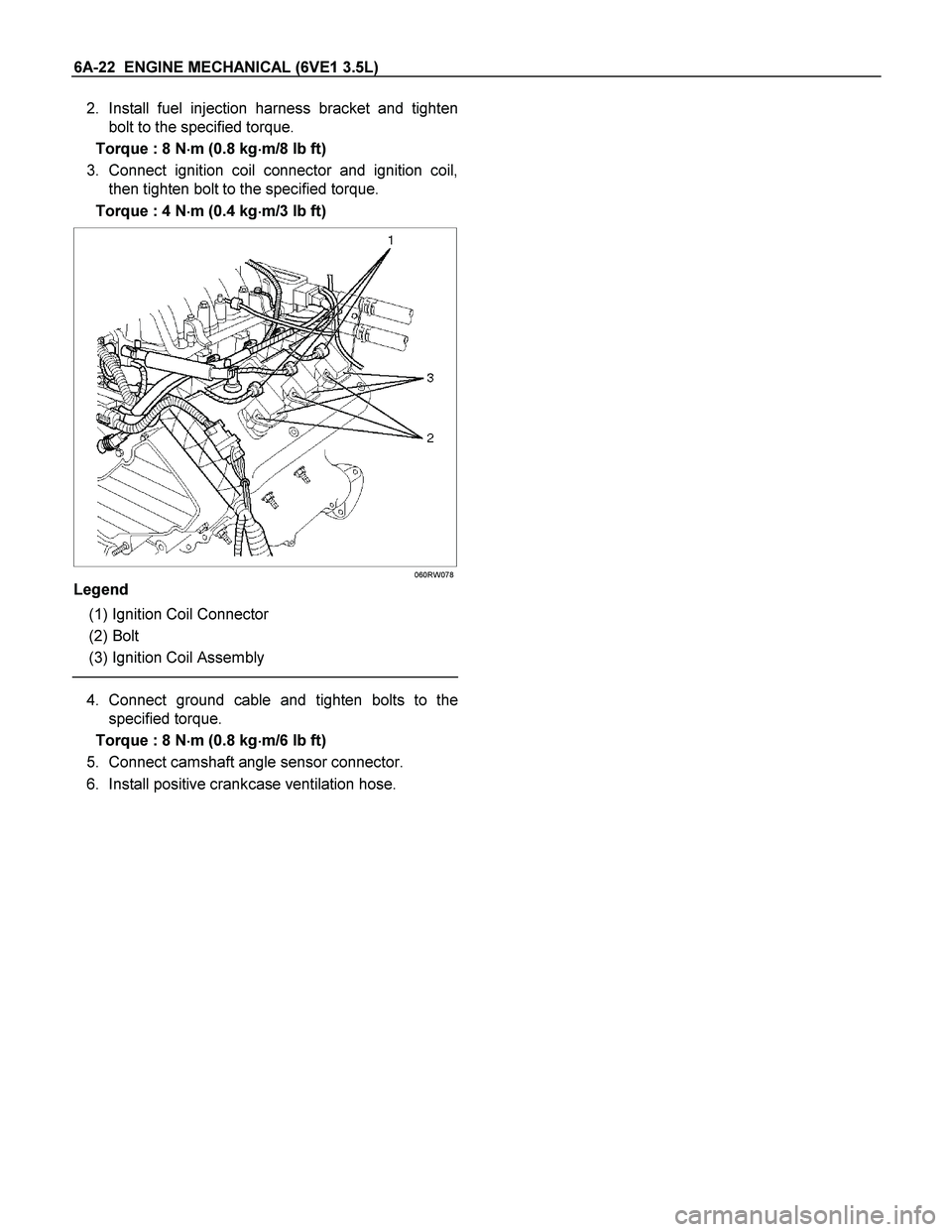
2. Install fuel injection harness bracket and tighten
bolt to the specified torque.
Torque : 8 N�
�� �m (0.8 kg�
�� �m/8 lb ft)
3. Connect ignition coil connector and ignition coil,
then tighten bolt to the specified torque.
Torque : 4 N�
�� �m (0.4 kg�
�� �m/3 lb ft)
060RW078
Legend
(1) Ignition Coil Connector
(2) Bolt
(3) Ignition Coil Assembly
4. Connect ground cable and tighten bolts to the
specified torque.
Torque : 8 N�
�� �m (0.8 kg�
�� �m/6 lb ft)
5. Connect camshaft angle sensor connector.
6. Install positive crankcase ventilation hose.
Page 1847 of 4264
 6A-23
Cylinder Head Cover RH
Removal
1. Disconnect battery ground cable.
2. Remove air cleaner duct assembly.
3. Disconnect ventilation hose from cylinder head
cove")
ENGINE MECHANICAL (6VE1 3.5L) 6A-23
Cylinder Head Cover RH
Removal
1. Disconnect battery ground cable.
2. Remove air cleaner duct assembly.
3. Disconnect ventilation hose from cylinder head
cover.
4. Disconnect three ignition coil connectors from
ignition coils and remove harness bracket bolts on
cylinder head cover then remove ignition coil fixing
bolts on ignition coils and remove ignition coils.
5. Remove heater pipe fixing bolts from the bracket.
6. Disconnect fuel injector harness connector then
remove fuel injector harness bracket bolt.
7. Remove eight fixing bolts then the cylinder head
cover.
010RW002
Installation
1. Install cylinder head cover.
� Clean the sealing surface of cylinder head and
cylinder head cover to remove oil and sealing
materials completely.
� Apply sealant (TB-1207B or equivalent) of bead
diameter 2‐3 mm at eight place of arched
area of camshaft bracket on front and rea
r
sides.
� The cylinder head cover must be installed
within 5 minutes after sealant application to
prevent premature hardening of sealant.
� Tighten bolts to the specified torque.
Torque : 9 N�
�� �m (0.9 kg�
�� �m/7 lb ft)
014RW019
2. Install exhaust gas recirculation pipe and tighten to
specified torque.
Torque :
Exhaust manifold side: 29 N�
�� �m (3.0 kg�
�� �m/21 lb ft)
Flare nut: 44 N�
�� �m (4.5 kg�
�� �m/33 lb ft)
Cylinder head side: 20 N�
�� �m (2.0 kg�
�� �m/14 lb ft)
3. Tighten fuel injector harness bracket bolts to
specified torque then reconnect fuel injecto
r
harness connector.
Torque : 8 N�
�� �m (0.8 kg�
�� �m/5.7 lb ft)
4. Install heater pipe bolt to the specified torque.
Torque : 20 N�
�� �m (2.0 kg�
�� �m/14 lb ft)
5. Connect ignition coil connector and tighten ignition
coil fixing bolts to specified torque.
Torque : 4 N�
�� �m (0.4 kg�
�� �m/3 lb ft)
6. Connect ventilation hose to cylinder head.
7. Install air cleaner duct assembly.
Page 1849 of 4264
 6A-25
Installation
1. Install throttle body and tighten bolts to the
specified torque.
Torque : 25 N�
�� �m (2.5 kg�
�� �m/18 lb ft)
2. Install common chamber and ti")
ENGINE MECHANICAL (6VE1 3.5L) 6A-25
Installation
1. Install throttle body and tighten bolts to the
specified torque.
Torque : 25 N�
�� �m (2.5 kg�
�� �m/18 lb ft)
2. Install common chamber and tighten bolts and
nuts to the specified torque.
Torque :
Bolt : 18 N�
�� �m (1.8 kg�
�� �m/13 lb ft)
Nut : 18 N�
�� �m (1.8 kg�
�� �m/13 lb ft)
3. Install fuel hose bracket and tighten bolts to
specified torque.
Torque : 10 N�
�� �m (1.0 kg�
�� �m/89 lb in)
4. Install ventilating hose to throttle valve and intake
duct.
5. Connect vacuum hoses on canister VSV and
positive crankcase ventilation hose. Tighten bolts
for fuel rail assembly with pressure control valve
bracket.
Torque : 25 N�
�� �m (2.5 kg�
�� �m/18 lb ft)
6. Connect each connector without fail.
7. Connect vacuum booster hose.
8. Install the ECM.
� Tighten the four bolts.
Torque : 10 N�
�� �m (1.0 kg�
�� �m/7 lb ft)
� Connect the two connectors.
� Tighten the two ground cable bolts.
9. Install accelerator control cable to accelerato
r
cable bracket.
� Rotate the ratchet ring in direction an arrow 90�
� Confirm marking of outer cap must be uppe
r
side.
� Slider the lock of outer cap must be upper side.
� Confirm ratchet ring is locked.
060RW093
Legend
(1) Cable Bracket
(2) Ratchet ring
(3) Outer Cap
(4) Lock
(5) Paint Mark
(6) Arrow Mark
10. Install the cable clips to accelerator control cable.
11. Install air cleaner duct assembly.