Page 1894 of 4264
6A-70 ENGINE MECHANICAL (6VE1 3.5L)
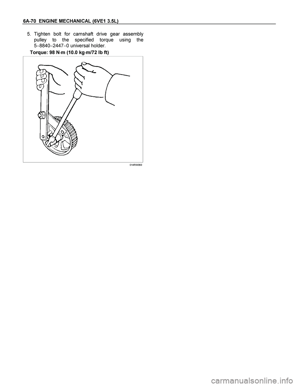
5. Tighten bolt for camshaft drive gear assembly
pulley to the specified torque using the
5�8840�2447�0 universal holder.
Torque: 98 N�
�� �m (10.0 kg�
�� �m/72 lb ft)
014RW060
Page 1896 of 4264

3. Remove oil pipe and O-ring (3).
4. Remove oil strainer and O-ring (4).
5. Remove oil pump assembly (5).
6. Remove crankcase side bolts (6).
7. Remove oil g")
6A-72 ENGINE MECHANICAL (6VE1 3.5L)
3. Remove oil pipe and O-ring (3).
4. Remove oil strainer and O-ring (4).
5. Remove oil pump assembly (5).
6. Remove crankcase side bolts (6).
7. Remove oil gallery (7).
8. Remove piston and connecting rod assembly (8).
Refer to “Piston, Piston Ring and Connecting Rod"
in this manual.
9. Remove flywheel (9).
10. Remove rear oil seal retainer (10).
11. Remove main bearing cap (11).
12. Remove crankshaft (12).
Inspection and Repair
1. Crankshaft
Set the dial indicator as shown in the illustration
and measure the crankshaft thrust clearance. I
f
the thrust clearance exceeds the specified limit,
replace the thrust bearings as a set.
Thrust Clearance
Standard : 0.06 mm�
�� �0.24 mm
(0.0024 in�
�� �0.0094 in)
Limit : 0.30 mm (0.0118 in)
015RS003
Main Bearing Clearance
1. Remove the bearing caps and measure the oil
clearance.
2. Remove the main bearing cap fixing bolts in the
sequence shown in the illustration.
Arrange the removed main bearing caps in the
cylinder number order.
Remove the main bearings.
015RS004
3. Remove the crankshaft. Remove the main
bearings.
4. Clean the upper and lower bearings as well as the
crankshaft main journal.
5. Check the bearings for damage or excessive wear.
The bearings must be replaced as a set if damage
or excessive wear is discovered during inspection.
6. Set the upper bearings and the thrust washers to
their original positions.
Carefully install the crankshaft.
7. Set the lower bearings to the bearing cap original
position.
8.
Apply plastigage to the crankshaft journal unit as
shown in the illustration.
NOTE: Do not set the plastigage on the oil hole.
015RS005
9. Install main bearing caps, oil gallery and crank
case bolts in the order shown, and tighten each
bolt to the specified torque.
NOTE: Do not apply engine oil to the crank case side
Page 1897 of 4264
 6A-73
bolts.
Main bearing cap bolts.
Torque: 39 N�
�� �m (4.0 Kg�
�� �m/29 lb ft)
Oil gallery fixing bolts.
Torque:
1st step: 29 N�
�� �m (3.0 Kg�
�� �m/21 lb ft)")
ENGINE MECHANICAL (6VE1 3.5L) 6A-73
bolts.
Main bearing cap bolts.
Torque: 39 N�
�� �m (4.0 Kg�
�� �m/29 lb ft)
Oil gallery fixing bolts.
Torque:
1st step: 29 N�
�� �m (3.0 Kg�
�� �m/21 lb ft)
2nd step 55�
�� � �
�� � 65�
�� �
Crank case side bolts
Torque : 39 N�
�� �m (4.0 Kg�
�� �m/29 lb ft)
NOTE: Do not allow the crankshaft to rotate.
015RS006
10. Remove the main bearing caps in the sequence
shown in the illustration.
015RS004
11. Measure the plastigage width and determine the
oil clearance. If the oil clearance exceeds the
specified limit, replace the main bearings as a se
t
and/or replace the crankshaft.
Standard : 0.019 mm�
�� �0.043 mm
(0.0007 in�
�� �0.0017 in)
Limit : 0.08 mm (0.0031 in)
015RS008
12. Clean the plastigage from the bearings and the
crankshaft.
Remove the crankshaft and the bearings.
Crankshaft (12) Inspection
Inspect the surface of the crankshaft journal and crank
pins for excessive wear and damage. Inspect the oil
seal fitting surfaces for excessive wear and damage.
Inspect the oil ports for obstructions.
Inspection and Repair
1. Carefully set the crankshaft on the V�blocks.
Slowly rotate the crankshaft and measure the
runout. If the crankshaft runout exceeds the
specified limit, the crankshaft must be replaced.
Runout : 0.04 mm (0.0016 in)
015RS007
Page 1900 of 4264

015RW002
Legend
(1) Around Bolt Holes
(2) Around Dowel Pin
� Apply engine oil to the oil seal lip.
�
Align the cylinder block dowel pin holes wi")
6A-76 ENGINE MECHANICAL (6VE1 3.5L)
015RW002
Legend
(1) Around Bolt Holes
(2) Around Dowel Pin
� Apply engine oil to the oil seal lip.
�
Align the cylinder block dowel pin holes with the
rear retainer dowel pins.
� Tighten the rear retainer fixing bolts. New bolts
should be used when installing rear retainer.
Torque: 18 N�
�� �m (1.8 Kg�
�� �m/13 lb ft)
NOTE: Be very careful not to disengage the oil seal
garter spring during installation of the rear retainer.
If the seal was removed from retainer fo
r
replacement, apply engine oil to the oil seal lip
and install the oil seal using 5�8840�2286�0 oil
seal installer.
015RW001
015RS017
3. Flywheel (9)
1. Thoroughly clean and remove the oil from the
threads of crankshaft.
2. Remove the oil from the crankshaft and
flywheel mounting faces.
3. Mount the flywheel on the crankshaft and then
install the washer.
4. Hold the crankshaft to prevent from rotating
then install the bolts in the order shown to the
specified torque.
Torque: 54 N�
�� �m (5.5 Kg�
�� �m/40 lb ft)
NOTE: Do not reuse the bolt and do not apply oil o
r
thread lock to the bolt.
015RS018
4. Piston and connecting rod assembly (8)
�
Apply engine oil to the cylinder bores, the
connecting rod bearings and the crankshaf
t
pins. Check to see that the piston ring end gaps
are correctly positioned.
Page 1901 of 4264
 6A-77
015RS019
Legend
(1) No.1 Compression Ring
(2) No.2 Compression Ring
(3) Oil Ring Side Rail Upper
(4) Oil Ring Side Rail Lower
(5) Piston Front Ma")
ENGINE MECHANICAL (6VE1 3.5L) 6A-77
015RS019
Legend
(1) No.1 Compression Ring
(2) No.2 Compression Ring
(3) Oil Ring Side Rail Upper
(4) Oil Ring Side Rail Lower
(5) Piston Front Mark
� Insert the piston/connecting rod assemblies into
each cylinder with the piston ring compressor.
The front marks must be facing the front of the
engine.
� Match the numbered caps with the numbers on
the connecting rods. Align the punched marks
on the connecting rods and caps.
� Apply engine oil to the threads and seating
faces of the nuts.
� Tighten the nuts.
Torque: 54 N�
�� �m (5.5 Kg�
�� �m/40 lb ft)
After tightening the cap nuts, check to see that
the crankshaft rotates smoothly.
NOTE: Do not apply engine oil to the bearing back
faces.
015RS020
5. Install oil gallery (7) and tighten the bolts in 2
steps, in the order shown.
1st step: 29 N�
�� �m (3.0 Kg�
�� �m/22 lb ft)
2nd step: 55�
�� � �
�� � 65�
�� �
051RS009
6. Cylinder block side bolts (6)
� Tighten all the bolts to the specified torque in
the order shown.
NOTE: Do not apply engine oil to the crank case side
bolts.
Torque: 39 N�
�� �m (4.0 Kg�
�� �m/29 lb ft)
Page 1902 of 4264
6A-78 ENGINE MECHANICAL (6VE1 3.5L)
012RS001
7. Install oil pump assembly (5), refer to “Oil pump" in
this manual.
8. Install oil strainer and O-ring (4).
9. Install oil pipe and O-ring (3) and tighten the bolts.
Torque: 25 N�
�� �m (2.5 Kg�
�� �m/18 lb ft)
10. Install crankcase with oil pan (2).
1. Completely remove all residual sealant,
lubricant and moisture from the sealing
surfaces. The surfaces must be perfectly dry.
2. Apply a correct width bead of sealant (TB
�
1207C or its equivalent) to the contact surfaces
of the oil pan. There must be no gaps in the
bead.
3. The crankcase assembly must be installed
within 5 minutes after sealant application to
prevent premature hardening of the sealant.
4. Tighten the bolts and nuts to the specified
torque.
Torque : 10 N�
�� �m (1.0 Kg�
�� �m/7 lb ft)
013RW010
Legend
(1) Portion Between Bolt Holes
(2) Bolt Hole Portion
11. Install cylinder head assembly, refer to “Cylinder
head" in this manual.
Page 1907 of 4264
 6A-83
3. Insert the new pin into the piston and rotate it. If
the pin rotates smoothly with no backlash, the
clearance is normal. If there is backlash o
r
roughness, me")
ENGINE MECHANICAL (6VE1 3.5L) 6A-83
3. Insert the new pin into the piston and rotate it. If
the pin rotates smoothly with no backlash, the
clearance is normal. If there is backlash o
r
roughness, measure the clearance. If the
clearance exceeds the specified limit, the piston
must be replaced.
Clearance
Standard : 0.010 mm�
�� �0.017 mm
(0.0004 in. �
�� �0.0007 in)
Limit : 0.040 mm (0.0016 in)
Connecting Rods (11)
1. Check the connecting rod alignment If either the
bend or the twist exceeds the specified limit, the
connecting rod must be replaced.
Bend per 100 mm (3.937 in)
Limit: 0.15 (0.0059)
Twist per 100 mm (3.937 in)
Limit: 0.20 (0.0078)
015RS030
2. Measure the connecting rod thrust clearance. Use
a feeler gauge to measure the thrust clearance a
t
the large end of the connecting rod If the clearance
exceeds the specified limit, the connecting rod
must be replaced.
Standard : 0.16 mm�
�� �0.35 mm
(0.0063 in. �
�� �0.0138 in)
Limit : 0.40 mm (0.0157 in)
015RS031
3. Measure the oil clearance between the connecting
rod and the crankshaft.
1. Remove the connecting rod cap nuts and the
rod caps (12).
Arrange the removed rod caps in the cylinder
number order.
2. Clean the rod bearings and the crankshaft pins.
3. Carefully check the rod bearings. If even one
bearing is found to be damaged or badly worn,
the entire bearing assembly must be replaced
as a set. Reinstall the bearings in their original
positions. Apply plastigage to the crank pin.
015RS032
4. Reinstall the rod caps (12) to their original
positions.
Tighten the rod cap nuts.
Torque: 54 N�
�� �m (5.5 kg�
�� �m/40 lb ft)
Page 1910 of 4264
6A-86 ENGINE MECHANICAL (6VE1 3.5L)
5. Install piston and connecting rod assembly.
� Insert the bearings into the connecting rods and
caps. Apply new engine oil to the bearing faces
and nuts.
� Tighten the connecting rod cap nuts
Torque : 54 N�
�� �m (5.5 kg�
�� �m/40 lb ft)
NOTE: Do not apply engine oil to the bearing back
faces.
6. Oil gallery, refer to “Crankshaft and main bearing"
in this manual.
7. Oil strainer and O-ring.
8. Oil pipe and O-ring.
9. Install crankcase with oil pan, refer to “Oil pan and
Crankcase" in this manual.
10. Install cylinder head gasket.
11. Install Cylinder head assembly.
� Refer to “Cylinder head" in this manual.

012RS001
7. Install oil pump assembly (5), refer to “Oil pump\" in
this manual.
8. Install oil strainer and O-ring (4).
9. Install oil pipe and O-ring (")