Page 1939 of 4264
 6B-15
Drive Belt and Cooling Fan
Drive Belt and Associated Parts
015RW005
Legend (4) Water Pump and Cooling Fan Pulley
(1) Crankshaft Pulley (5) Idle Pulley")
ENGINE COOLING (6VE1 3.5L) 6B-15
Drive Belt and Cooling Fan
Drive Belt and Associated Parts
015RW005
Legend (4) Water Pump and Cooling Fan Pulley
(1) Crankshaft Pulley (5) Idle Pulley
(2) Generator (6) Tension Pulley
(3) Power Steering Pump (7) Drive Belt
The drive belt adjustment is not required as automatic
drive belt tensioner is equipped.
Inspection
Check drive belt for wear or damage, and replace with a
new one as necessary.
Installation
Install cooling fan assembly and tighten bolts/nuts to the
specified torque.
Torque : 25 N�
�� �m (2.5 kg�
�� �m/18 lb ft) for fan pulley
and fan bracket.
Torque : 10 N�
�� �m (1.0 kg�
�� �m/7 lb ft) for fan and
clutch assembly.
NOTE: Fan belts for 6VE1 Gasoline Engine mounted on
98MY (UX) have been brought into one. As a result, the
rotating direction of a fan belt is opposite to the direction
of cooling fan for 92 to 97MY 6VD1 with no
interchangeability.
Therefore, incorrect installation of a fan may cause the
air for cooling to flow in the opposite direction, this
resulting in the poor performance of the air-conditione
r
and a rise temperature in engine cooling water.
Page 1941 of 4264
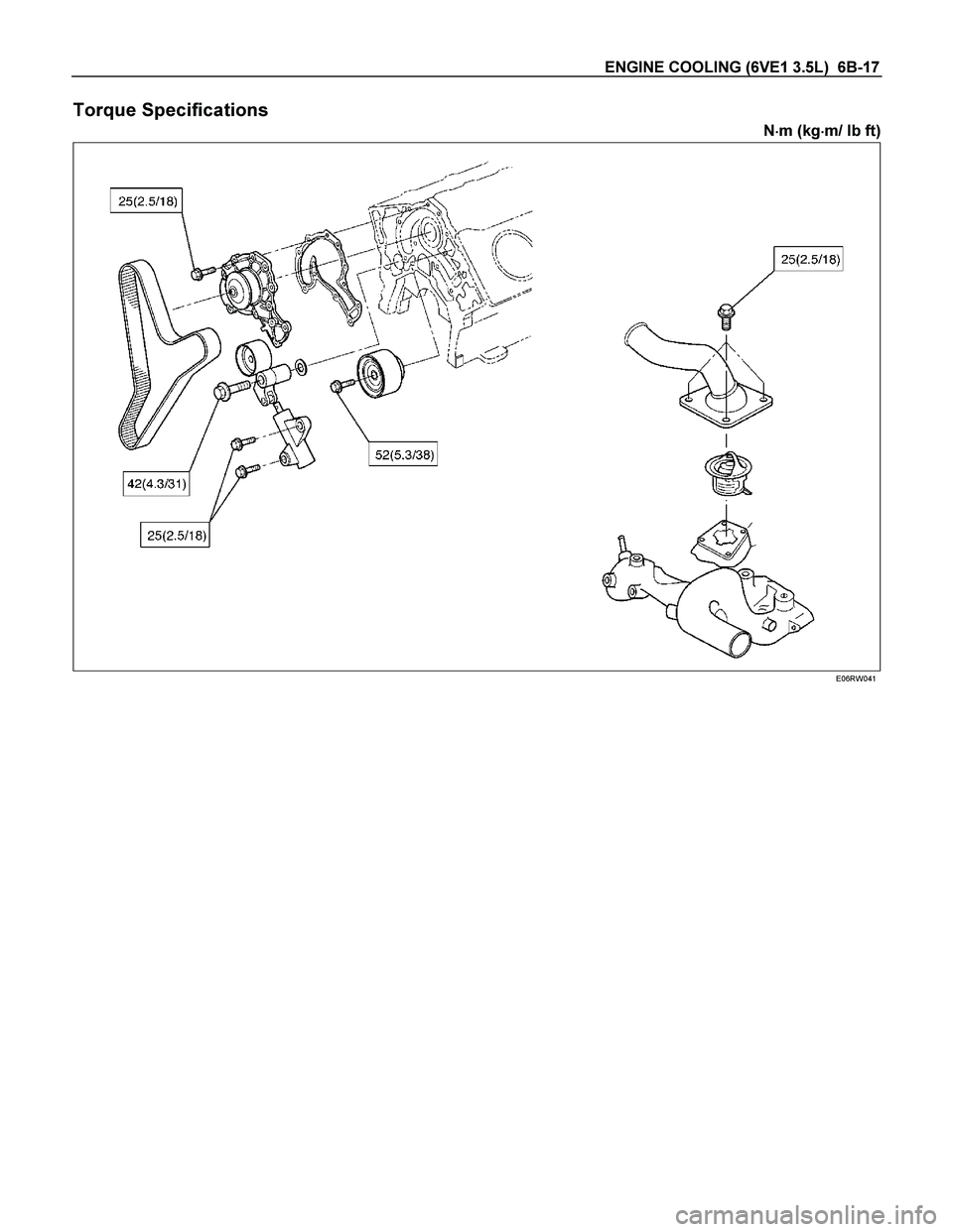
ENGINE COOLING (6VE1 3.5L) 6B-17
Torque Specifications
N�
�� �m (kg�
�� �m/ lb ft)
E06RW041
Page 1954 of 4264

Removal
CAUTION: When repair to the fuel system has been
completed, start engine and check the fuel system
for loose connection or leakage. For the fuel system
diagno")
6C-12 ENGINE FUEL (6VE1 3.5L)
Removal
CAUTION: When repair to the fuel system has been
completed, start engine and check the fuel system
for loose connection or leakage. For the fuel system
diagnosis, see Section “Driveability and Emission".
1. Disconnect battery ground cable.
2. Loosen slowly the fuel filler cap.
NOTE: To prevent spouting out fuel to change the
pressure in the fuel tank.
NOTE: Cover opening of the filler neck to prevent any
dust entering.
3. Jack up the vehicle.
4. Support underneath of the fuel tank with a lifter.
5. Remove the inner liner of the wheel house on rea
r
left side.
6. Remove fasten bolt to the filler neck from the
body.
7. Disconnect the quick connector (8) into the fuel
tube from the fuel pipe and the evapo tube from
evapo joint connector.
NOTE: Cover the quick connector to prevent any dus
t
entering and fuel leaking.
NOTE: Refer to “Fuel Tube/Quick Connector Fittings” in
this section when performing any repairs.
8. Remove fasten bolt (1) to the tank band and the
tank band (2).
9. Disconnect the pump and sender connector on the
fuel pump and remove the harness from weld clip
on the fuel tank.
10. Lower the fuel tank (6).
NOTE: When the fuel tank is lowered from the vehicle,
don’t scratch each hose and tube by around other pars.
Installation
1. Rise the fuel tank into position.
NOTE: Ensure hoses and tubes do not foul on othe
r
component.
2. Connect the pump and sender connector to the
fuel pump and install harness to into the plastic clip
welded to the top of the fuel tank..
NOTE: The connector must be certainly connected
against stopper.
Ensure tank band anchor mates with guide hole on
frame.
3. Install the tank band to fasten bolt.
Torque: 68 N�
�� �m (6.9kg�
�� �m/50 lb ft)
NOTE: The anchor of the tank band must be certainly
installed to guide hole on frame.
4. Connect the quick connector from the fuel tube to
the fuel pipe and the evapo tube from evapo join
t
connector.
NOTE: Pull off the left checker into the fuel pipe.
NOTE: Refer to “Fuel Tube/Quick Connector Fittings” in
this section when performing any repairs.
5. Install the filler neck to the body by bolt.
6. Install the inner liner of the wheel house on rea
r
side.
7. Remove lifter to support underneath of the fuel
tank.
8. Put back the vehicle.
9. Tigten the filler cap until at least three clicks are
heard.
10. Connect the battery ground cable.
Page 1955 of 4264
 6C-13
Filler Neck
Removal
1. Remove the fuel tank.
NOTE: Refer to \"Fuel Tank\" in this section.
2. Put a marking the following point as the filler neck
assembly is restore")
ENGINE FUEL (6VE1 3.5L) 6C-13
Filler Neck
Removal
1. Remove the fuel tank.
NOTE: Refer to "Fuel Tank" in this section.
2. Put a marking the following point as the filler neck
assembly is restored.
� Each joint area of the hose (to restore axial
direction and insertion length of the hose)
� Each fasten area of the clamp (to restore axial
direction and position of the clamp)
� Each bolt in the clamp (to restore fasten length
of bolt in the clamp)
� The band clip (to restore position and fasten
length of the band clip)
NOTE: Cover end of each hose and pipe to prevent any
dust entering.
Installation
1. Align each marking and restore the following point.
� Each joint area of the hose (Restore axial
direction and insertion length of the hose)
� Each fasten area of the clamp (Restore axial
direction and position of the clamp)
� Each bolt in the clamp (Restore fasten length o
f
bolt in the clamp)
Torque: 2.5 N�
�� �m (0.25 kg�
�� �m / 2 lb ft) … filler neck
side except flat deck model.
� The band clip (Restore position and fasten
length of the band clip)
2. Install the fuel tank.
NOTE: Refer to "Fuel Tank" in this section.
Fuel Gauge Unit
Removal and Installation
As for removal and installation of the Fuel Gauge Unit,
refer to “Fuel Tank" of this section 6C as the fuel gauge
unit is combined with the fuel pump and sende
r
assembly.
Page 1957 of 4264
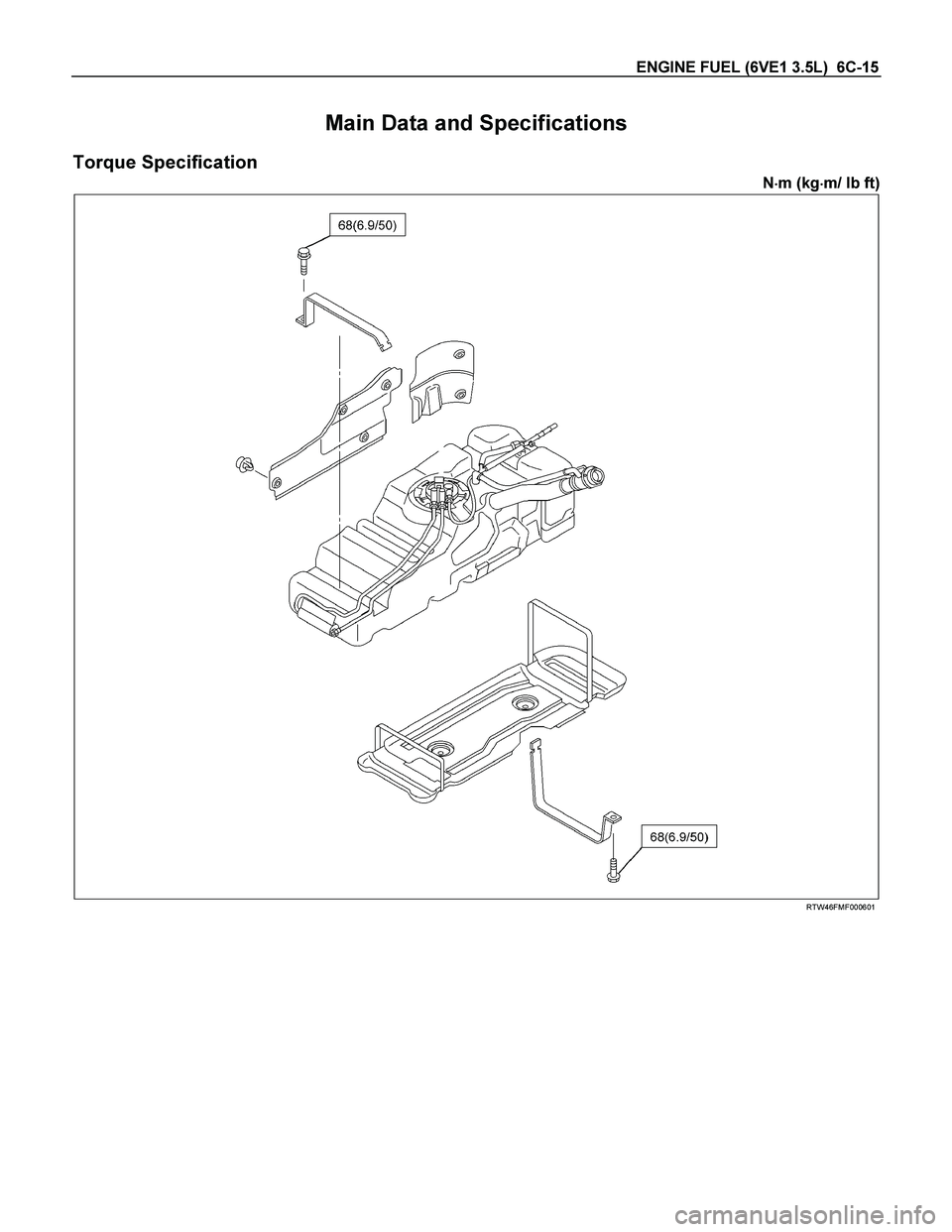
ENGINE FUEL (6VE1 3.5L) 6C-15
Main Data and Specifications
Torque Specification
N�
�� �m (kg�
�� �m/ lb ft)
RTW46FMF000601
Page 1959 of 4264
 6D1-1
ENGINE
ENGINE ELECTRICAL (6VE1 3.5L)
CONTENTS
Service Precaution................................................. 6D1-1
Battery.............................")
ENGINE ELECTRICAL (6VE1 3.5L) 6D1-1
ENGINE
ENGINE ELECTRICAL (6VE1 3.5L)
CONTENTS
Service Precaution................................................. 6D1-1
Battery...................................................................... 6D1-2
General Description............................................ 6D1-2
Diagnosis............................................................. 6D1-2
Battery Charging................................................. 6D1-3
Jump Starting....................................................... 6D1-3
Battery Removal.................................................. 6D1-4
Battery Installation............................................... 6D1-4
Main Data and Specifications................................ 6D1-5
Service Precaution
WARNING: THIS VEHICLE HAS A SUPPLEMENTAL
RESTRAINT SYSTEM (SRS). REFER TO THE SRS
COMPONENT AND WIRING LOCATION VIEW IN
ORDER TO DETERMINE WHETHER YOU ARE
PERFORMING SERVICE ON OR NEAR THE SRS
COMPONENTS OR THE SRS WIRING. WHEN YOU
ARE PERFORMING SERVICE ON OR NEAR THE
SRS COMPONENTS OR THE SRS WIRING, REFE
R
TO THE SRS SERVICE INFORMATION. FAILURE TO
FOLLOW WARNINGS COULD RESULT IN
POSSIBLE AIR BAG DEPLOYMENT, PERSONAL
INJURY, OR OTHERWISE UNNEEDED SRS SYSTEM
REPAIRS.
CAUTION: Always use the correct fastener in the
proper location. When you replace a fastener, use
ONLY the exact part number for that application.
ISUZU will call out those fasteners that require a
replacement after removal. ISUZU will also call out
the fasteners that require thread lockers or thread
sealant. UNLESS OTHERWISE SPECIFIED, do not
use supplemental coatings (Paints, greases, o
r
other corrosion inhibitors) on threaded fasteners or
fastener joint interfaces. Generally, such coatings
adversely affect the fastener torque and the joint
clamping force, and may damage the fastener.
When you install fasteners, use the correct
tightening sequence and specifications. Following
these instructions can help you avoid damage to
parts and systems.
Page 1965 of 4264
 6D2-1
ENGINE
IGNITION SYSTEM (6VE1 3.5L)
CONTENTS
Service Precaution................................................. 6D2-1
General Description.....................")
IGNITION SYSTEM (6VE1 3.5L) 6D2-1
ENGINE
IGNITION SYSTEM (6VE1 3.5L)
CONTENTS
Service Precaution................................................. 6D2-1
General Description............................................... 6D2-2
Diagnosis................................................................. 6D2-2
Ignition Coil.............................................................. 6D2-3
Removal............................................................... 6D2-3
Inspection and Repair........................................ 6D2-3
Installation............................................................ 6D2-3
Spark Plug............................................................... 6D2-4
Inspection............................................................. 6D2-4
Replacement spark plugs................................... 6D2-4
Crankshaft Position Sensor................................... 6D2-5
Removal................................................................ 6D2-5
Installation............................................................. 6D2-5
Main Data and Specifications................................ 6D2-6
Service Precaution
WARNING: THIS VEHICLE HAS A SUPPLEMENTAL
RESTRAINT SYSTEM (SRS). REFER TO THE SRS
COMPONENT AND WIRING LOCATION VIEW IN
ORDER TO DETERMINE WHETHER YOU ARE
PERFORMING SERVICE ON OR NEAR THE SRS
COMPONENTS OR THE SRS WIRING. WHEN YOU
ARE PERFORMING SERVICE ON OR NEAR THE
SRS COMPONENTS OR THE SRS WIRING, REFE
R
TO THE SRS SERVICE INFORMATION. FAILURE TO
FOLLOW WARNINGS COULD RESULT IN
POSSIBLE AIR BAG DEPLOYMENT, PERSONAL
INJURY, OR OTHERWISE UNNEEDED SRS SYSTEM
REPAIRS.
CAUTION: Always use the correct fastener in the
proper location. When you replace a fastener, use
ONLY the exact part number for that application.
ISUZU
will call out those fasteners that require a
replacement after removal. ISUZU will also call out
the fasteners that require thread lockers or thread
sealant. UNLESS OTHERWISE SPECIFIED, do not
use supplemental coatings (Paints, greases, o
r
other corrosion inhibitors) on threaded fasteners or
fastener joint interfaces. Generally, such coatings
adversely affect the fastener torque and the joint
clamping force, and may damage the fastener.
When you install fasteners, use the correct
tightening sequence and specifications. Following
these instructions can help you avoid damage to
parts and systems.
Page 1967 of 4264
 6D2-3
Ignition Coil
Removal
1. Disconnect battery ground cable.
2. Ignition coil connector and ignition coil.
Disconnect three connector from ignition coil.
R")
IGNITION SYSTEM (6VE1 3.5L) 6D2-3
Ignition Coil
Removal
1. Disconnect battery ground cable.
2. Ignition coil connector and ignition coil.
Disconnect three connector from ignition coil.
Remove harness bracket bolt on cylinder head
cover.
Remove fixing bolts on ignition coil.
RTW4Z0SH000101
Legend
(1) Ignition Coil Connector
(2) Bolt
(3) Ignition Coil Assembly
Inspection and Repair
Check the ignition coil assembly for insulation. Check
terminals for corrosion or damage, and replace as
necessary.
Measuring resistance of ignition coil assembly.
Terminal No. Limit
1 to 2 Without 0 ohm or infinity
maximum ohm.
1 to 3 Same as above
2 to 3 Same as above
Measure resistance of ignition coil assembly, and
replace the ignition coil assembly if its value exceeds
the standard.
060RW006
Installation
1. Install the ignition coil assembly (3).
Connect ignition coil connector (1) and ignition coil
(3), then tighten bolt (2) to the specified torque.
Torque: 4 N�
�� �m (0.4 kg�
�� �m/3 lb ft)
RTW4Z0SH000101
2. Connect battery ground cable.