Page 1914 of 4264

015RW002
Legend
(1) Around Bolt Holes
(2) Around Dowel Pin
� Apply engine oil to oil seal lip and align a dowel
pin hole in the cylinder block wit")
6A-90 ENGINE MECHANICAL (6VE1 3.5L)
015RW002
Legend
(1) Around Bolt Holes
(2) Around Dowel Pin
� Apply engine oil to oil seal lip and align a dowel
pin hole in the cylinder block with that in the
retainer.
� Tighten retainer fixing bolts to the specified
torque.
Torque: 25 N�
�� �m (2.5 kg�
�� �m/18.4 lb ft)
015RW001
4. Install flywheel
1. Thoroughly clean and remove the oil from the
threads of crankshaft.
2. Remove the oil from the crankshaft and
flywheel mounting faces.
3. Mount the flywheel on the crankshaft and then
install the washer.
4. Holding the crankshaft stationary, tighten the
flywheel bolts in the order shown. Torque: 54 N�
�� �m (5.5 kg�
�� �m/40 lb ft)
NOTE: Do not reuse the bolts and do not apply oil o
r
thread lock to the bolts.
015RS018
5. Install piston and connecting rod assembly.
� Apply engine oil to the cylinder bores, the
connecting rod bearings and the crankshaf
t
pins.
NOTE: Do not apply engine oil to the bearing back
faces.
� Check to see that the piston ring end gaps are
correctly positioned.
015RS019
Legend
(1) No.1 Compression Ring
(2) No.2 Compression Ring
(3) Oil Ring Side Rail Upper
(4) Oil Ring Side Rail Lower
(5) Piston Front Mark
Page 1915 of 4264
 6A-91
� Insert the piston/connecting rod assemblies into
each cylinder with the piston ring compressor.
� The front marks (1) must be facing the front o
f
the engine.")
ENGINE MECHANICAL (6VE1 3.5L) 6A-91
� Insert the piston/connecting rod assemblies into
each cylinder with the piston ring compressor.
� The front marks (1) must be facing the front o
f
the engine.
015RS020
6. Install oil gallery and tighten the bolts in 2 steps in
the order shown.
1st step : 29 N�
�� �m (3.0 kg�
�� �m/22 lb ft)
2nd step : 55�
�� � �
�� � 65°
012RS007
7. Install cylinder block side bolts (1) and tighten
crankcase bolts in sequence shown in the
illustration.
Torque : 39 N�
�� �m (4.0 kg�
�� �m/29 lb ft)
012RW005
8. Install oil pump assembly. Refer to “Oil Pump" in
this manual.
9. Install oil strainer and O-ring.
10. Install oil pipe and O-ring.
11. Install crankcase with oil pan.
1. Completely remove all residual sealant,
lubricant and moisture from the sealing
surfaces. The surfaces must be perfectly dry.
2. Apply a correct width bead of sealant (TB�
1207C or its equivalent) to the contact surfaces
of the crankcase. There must be no gaps in the
bead.
3. The oil pan must be installed within 5 minutes
after sealant application to prevent premature
hardening of sealant.
Page 1916 of 4264
6A-92 ENGINE MECHANICAL (6VE1 3.5L)
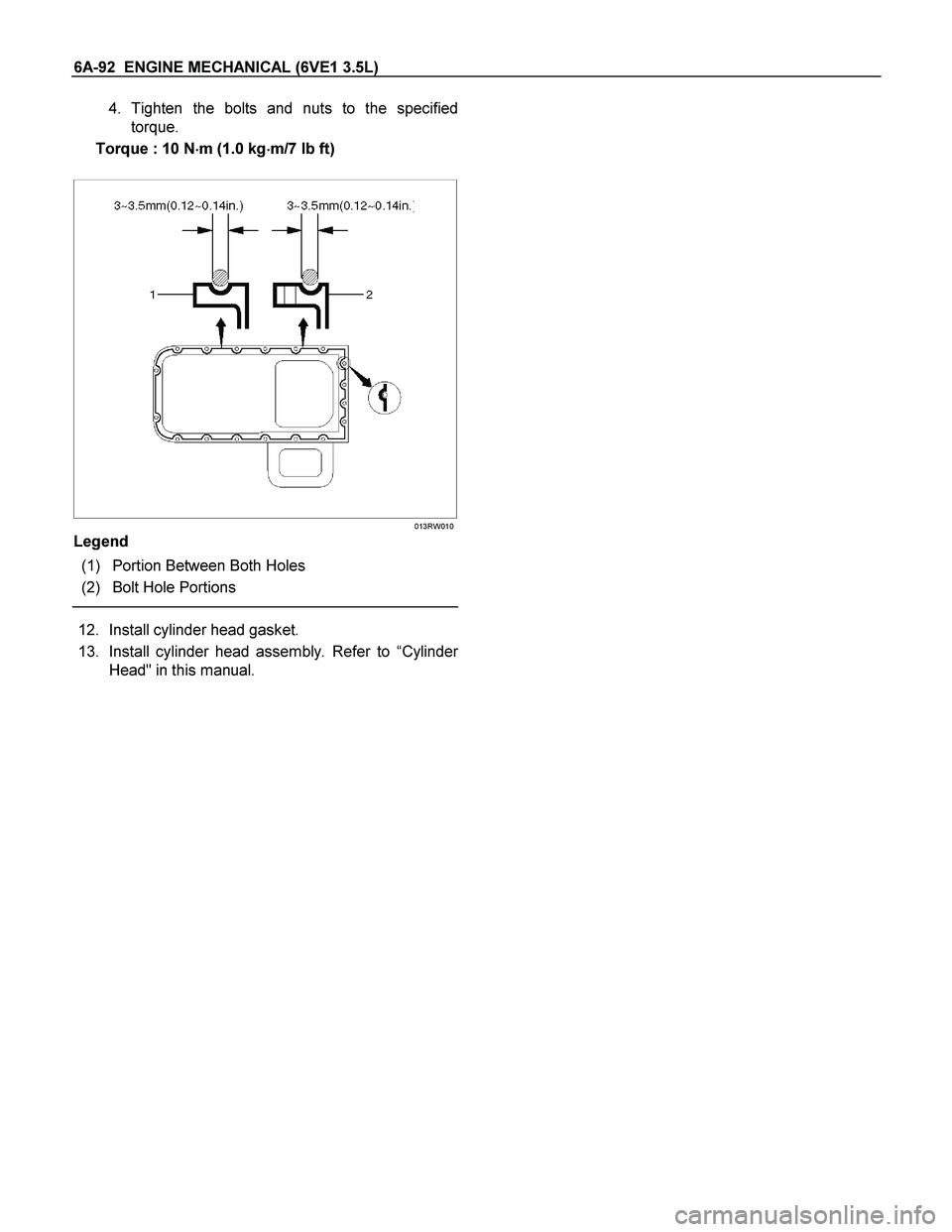
4. Tighten the bolts and nuts to the specified
torque.
Torque : 10 N�
�� �m (1.0 kg�
�� �m/7 lb ft)
013RW010
Legend
(1) Portion Between Both Holes
(2) Bolt Hole Portions
12. Install cylinder head gasket.
13. Install cylinder head assembly. Refer to “Cylinde
r
Head" in this manual.
Page 1918 of 4264
6A-94 ENGINE MECHANICAL (6VE1 3.5L)
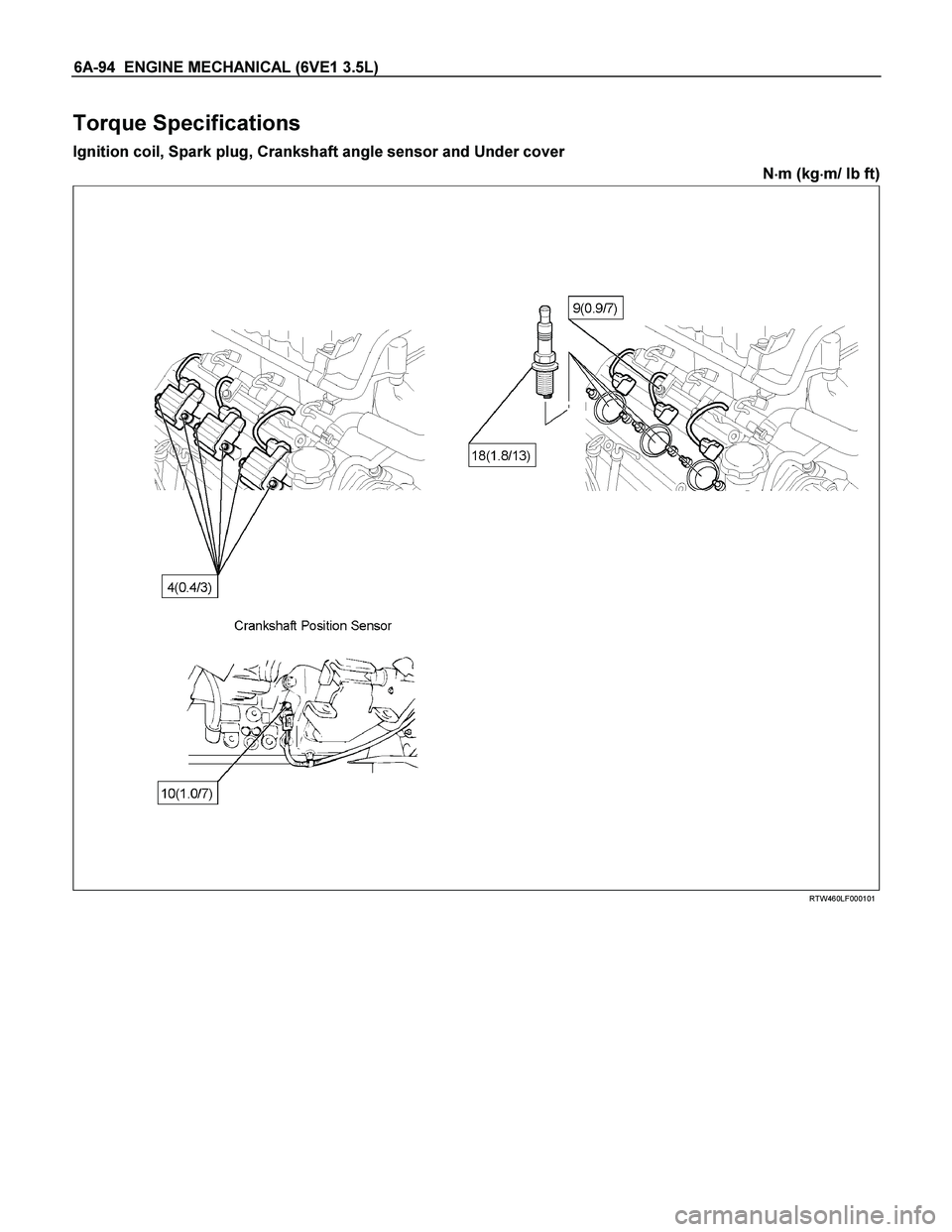
Torque Specifications
Ignition coil, Spark plug, Crankshaft angle sensor and Under cover
N�
�� �m (kg�
�� �m/ lb ft)
RTW460LF000101
Page 1925 of 4264
 6B-1
ENGINE
ENGINE COOLING (6VE1 3.5L)
CONTENTS
Service Precaution............................................. 6B–1
General Description .........................")
ENGINE COOLING (6VE1 3.5L) 6B-1
ENGINE
ENGINE COOLING (6VE1 3.5L)
CONTENTS
Service Precaution............................................. 6B–1
General Description ........................................... 6B–2
Diagnosis ........................................................... 6B–5
Draining and Refilling Cooling System .............. 6B–6
Water Pump ...................................................... 6B–7
Water Pump and Associated Parts ................ 6B–7
Removal ......................................................... 6B–7
Inspection ....................................................... 6B–7
Installation....................................................... 6B–7
Thermostat ........................................................ 6B–9
Thermostat and Associated Parts .................. 6B–9
Removal ......................................................... 6B–9
Inspection ....................................................... 6B–9
Installation ...................................................... 6B–9
Radiator ............................................................. 6B–10
Radiator and Associated Parts ....................... 6B–10
Removal ......................................................... 6B–11
Inspection ....................................................... 6B–11
Installation ...................................................... 6B–12
Drive Belt and Cooling Fan ................................ 6B–15
Drive Belt and Associated Parts ..................... 6B–15
Inspection ....................................................... 6B–15
Installation ...................................................... 6B–15
Main Data and Specifications ............................ 6B–16
Special Tool .................................................... 6B–18
Service Precaution
WARNING: THIS VEHICLE HAS A SUPPLEMENTAL
RESTRAINT SYSTEM (SRS). REFER TO THE SRS
COMPONENT AND WIRING LOCATION VIEW IN
ORDER TO DETERMINE WHETHER YOU ARE
PERFORMING SERVICE ON OR NEAR THE SRS
COMPONENTS OR THE SRS WIRING. WHEN YOU
ARE PERFORMING SERVICE ON OR NEAR THE
SRS COMPONENTS OR THE SRS WIRING, REFE
R
TO THE SRS SERVICE INFORMATION. FAILURE TO
FOLLOW WARNINGS COULD RESULT IN
POSSIBLE AIR BAG DEPLOYMENT, PERSONAL
INJURY, OR OTHERWISE UNNEEDED SRS SYSTEM
REPAIRS.
CAUTION: Always use the correct fastener in the
proper location. When you replace a fastener, use
ONLY the exact part number for that application.
ISUZU will call out those fasteners that require a
replacement after removal. ISUZU will also call out
the fasteners that require thread lockers or thread
sealant. UNLESS OTHERWISE SPECIFIED, do not
use supplemental coatings (Paints, greases, o
r
other corrosion inhibitors) on threaded fasteners or
fastener joint interfaces. Generally, such coatings
adversely affect the fastener torque and the joint
clamping force, and may damage the fastener.
When you install fasteners, use the correct
tightening sequence and specifications. Following
these instructions can help you avoid damage to
parts and systems.
Page 1931 of 4264
 6B-7
Water Pump
Water Pump and Associated Parts
030RS002
Legend
(1) Timing Belt (3) Water Pump Assembly
(2) Idle Pulley (4) Gasket
Removal
1. Disco")
ENGINE COOLING (6VE1 3.5L) 6B-7
Water Pump
Water Pump and Associated Parts
030RS002
Legend
(1) Timing Belt (3) Water Pump Assembly
(2) Idle Pulley (4) Gasket
Removal
1. Disconnect battery ground cable.
2. Drain coolant.
3. Radiator hose (on inlet pipe side).
4. Remove timing belt. Refer to “Timing Belt" in this
manual.
5. Remove Idle pulley.
6. Remove water pump assembly.
7. Remove gasket.
Inspection
Make necessary repair and parts replacement if
extreme wear or damage is found during inspection.
Should any of the following problems occur, the entire
water pump assembly must be replaced:
Crack in the water pump body
EC leakage from the seal unit
Play or abnormal noise in the bearing
Cracks or corrosion in the impeller.
Installation
1. Install gasket, clean the mating surface of gasket
before installation.
2. Install water pump assembly and tighten bolts to the
specified torque.
Torque: 25 N�
�� �m (2.5 kg�
�� �m/18 lb ft)
Tightening order
The tightening order are in the illustrate.
Page 1932 of 4264
6B-8 ENGINE COOLING (6VE1 3.5L)
NOTE: To prevent the oil leakage, apply the LOCTITE
262 or an equivalent, to the arrow marked fixing bol
t
thread.
030RW008
3. Idle pulley
Install idle pulley and tighten bolt to the specified
torque.
Torque: 52 N�
�� �m (5.3 kg�
�� �m/38 lb ft)
4. Timing belt
Install timing belt. Refer to timing belt installation
step in “Timing Belt" in this manual.
5. Connect radiator inlet hose and replenish EC.
6. Connect battery ground cable.
Page 1933 of 4264
 6B-9
Thermostat
Thermostat and Associated Parts
031RW001
Legend
(1) Thermostat Housing
(2) Thermostat
(3) Outlet Pipe
Removal
1. Disconnect battery grou")
ENGINE COOLING (6VE1 3.5L) 6B-9
Thermostat
Thermostat and Associated Parts
031RW001
Legend
(1) Thermostat Housing
(2) Thermostat
(3) Outlet Pipe
Removal
1. Disconnect battery ground cable.
2. Drain engine coolant from the radiator and engine.
3. Disconnect radiator hose from the inlet pipe.
4. Remove thermostat housing.
5. Remove thermostat(2).
Inspection
Suspend the thermostat in a water–filled container
using thin wire. Place a thermometer next to the
thermostat.
Do not directly heat the thermostat.
Gradually increase the water temperature. Stir the wate
r
so that the entire water is same temperature.
031RS003
Confirm the temperature when the valve first begins to
open.
Valve opening temperature 74.5�
�� �C �
�� � 78.5�
�� �C
(166.1�
�� �F �
�� � 173.3�
�� �F)
Confirm the temperature when the valve is fully opened.
Valve full open temperature and lift More than
8.5mm (0.33 in) at 90�
�� �C (194�
�� �F)
Make necessary repair and parts replacement i
f
extreme wear or damage is found during inspection.
Installation
1. Install thermostat into the outlet pipe(4) making sure
that the air hole is in the up position.
2. Install thermostat housing and tighten bolts to the
specified torque.
Torque: 25 N�
�� �m (2.5 kg�
�� �m/18 lb ft)
3. Installation rubber hose.
4. Replenish engine coolant (EC).
5. Start engine and check for EC leakage.

NOTE: To prevent the oil leakage, apply the LOCTITE
262 or an equivalent, to the arrow marked fixing bol
t
thread.
030RW008
3. Idle pulley
Install idle pul")