Page 1968 of 4264

Spark Plug
Inspection
Poor spark plug condition adversely affects engine
performance. Carefully inspect each spark plug
following the procedure outlined below.")
6D2-4 IGNITION SYSTEM (6VE1 3.5L)
Spark Plug
Inspection
Poor spark plug condition adversely affects engine
performance. Carefully inspect each spark plug
following the procedure outlined below.
1. Remove the spark plug.
2. Check the plug for dirt and other foreign material.
If the plug is extremely dirty, the fuel and electrical
systems must be checked.
3. If necessary, clean the spark plugs by placing them
in a spark plug cleaning machine for no more than
20 seconds.
4. Check the electrode and insulator for wear and/o
r
cracking. If there is significant wear or cracking, the
plug must be replaced.
5. Check the gasket for damage. Replace the gasket i
f
necessary.
6. Measure the insulation resistance with a 500-vol
t
megaohm meter. Replace the plug if the resistance
is less than the specified value.
Insulation resistance: 50 M
�
�� � or more
011RS010
7. Check the spark plug gap. Replace the spark plug
the if gap is not as specified.
Standard: 1.0–1.1 mm (0.04–0.043 in)
Limit: 1.3 mm (0.05 in)
011RS011
Do not attempt to adjust the gap of an old spark
plug. Replace the plug and adjust the gap of the
new plug if required.
Take care not to damage the spark plug tip
during handling.
8. Tighten the spark plugs to the specified torque.
Torque: 18 N�
�� �m (1.8 kg�
�� �m/13 lb ft)
Replacement spark plugs
Under normal conditions (no problem with the fuel
and/or electrical systems), use replacement spark
plugs with a low heat value (hot-type plug).
If insulator and electrode scorching is significant,
use replacement spark plugs with a high heat value
(cold-type plug).
Page 1969 of 4264
IGNITION SYSTEM (6VE1 3.5L) 6D2-5
Crankshaft Position Sensor
Removal
1. Disconnect battery ground cable
2. Wiring connector from crankshaft position sensor.
3. Remove crankshaft position sensor from cylinde
r
block.
012RS008
Installation
1. Install crankshaft position sensor into the cylinder
block.
Before installation, apply small amount of engine
oil to the O–ring.
Torque: 10 N�
�� �m (1.0 kg�
�� �m/7 lb ft)
2. Reconnect wiring connector to crankshaft position
sensor.
Page 1970 of 4264
6D2-6 IGNITION SYSTEM (6VE1 3.5L)
Main Data and Specifications
General Specifications
Ignition System
Ignition Form Electronic Ignition System (El system) with Crankshaft position sensor
Spark Plug
Type K16PR-P11
RC10PYP4
RK16PR11
Plug gap 1.0 mm (0.04 in) – 1.1 mm (0.043 in)
Torque 18 N�
�� �m (13lb ft)
Page 1971 of 4264
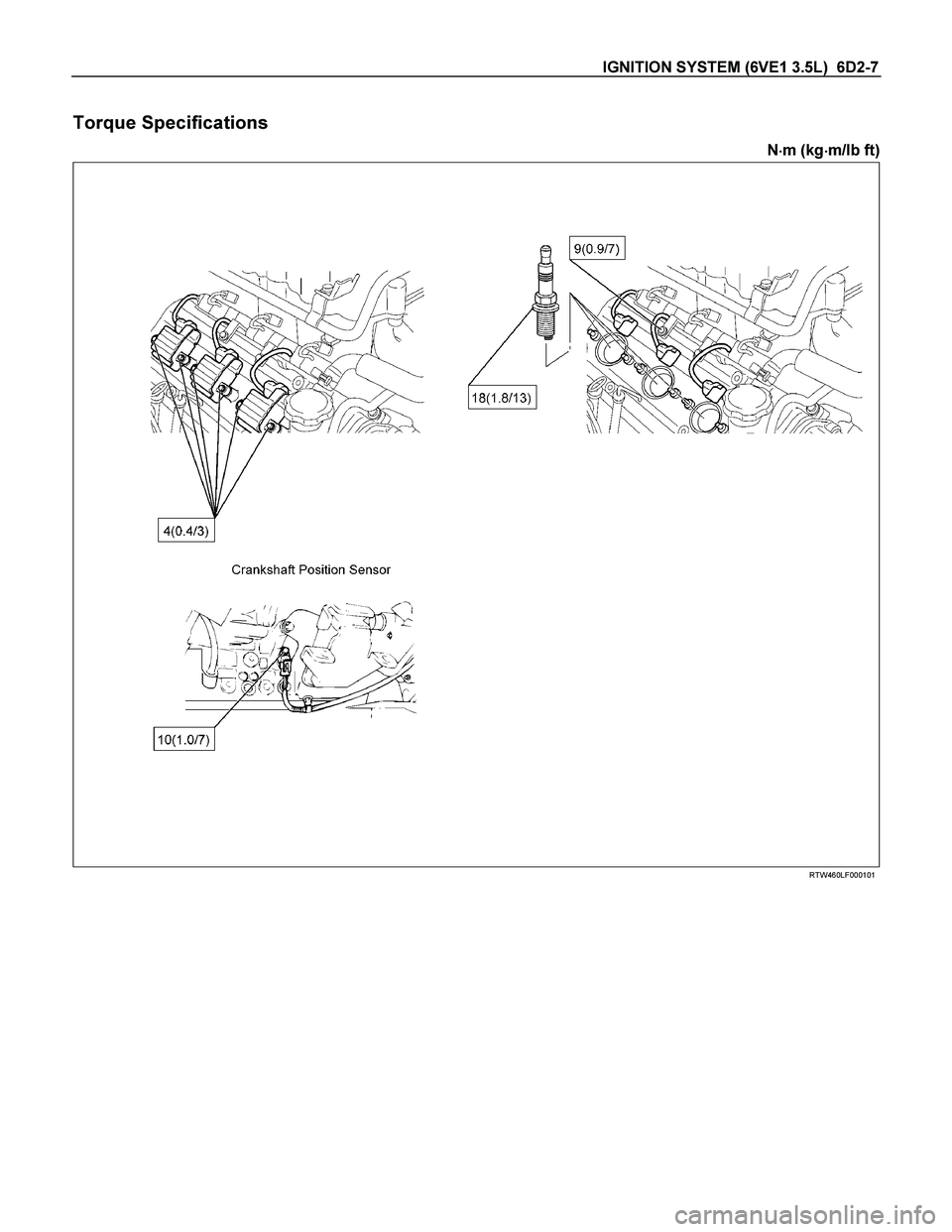
IGNITION SYSTEM (6VE1 3.5L) 6D2-7
Torque Specifications
N�
�� �m (kg�
�� �m/lb ft)
RTW460LF000101
Page 1973 of 4264
 6D3-1
ENGINE
STARTING AND CHARGING SYSTEM (6VE1 3.5L)
CONTENTS
Service Precaution................................................. 6D3-1
Starting Syste")
STARTING AND CHARGING SYSTEM (6VE1 3.5L) 6D3-1
ENGINE
STARTING AND CHARGING SYSTEM (6VE1 3.5L)
CONTENTS
Service Precaution................................................. 6D3-1
Starting System...................................................... 6D3-2
General Description............................................... 6D3-2
Diagnosis................................................................. 6D3-4
Starter...................................................................... 6D3-5
Removal............................................................... 6D3-5
Installation............................................................ 6D3-5
Disassembled View............................................ 6D3-6
Disassembly........................................................ 6D3-7
Inspection and Repair........................................ 6D3-9
Reassembly.........................................................6D3-12
Main Data and Specifications............................6D3-13
Charging System....................................................6D3-15
General Description................................................6D3-15
General On-Vehicle Inspection.............................6D3-15
Generator.................................................................6D3-16
Removal................................................................6D3-16
Inspection.............................................................6D3-16
Installation.............................................................6D3-16
Disassembled View.............................................6D3-17
Disassembly.........................................................6D3-17
Inspection and Repair.........................................6D3-20
Reassembly..........................................................6D3-22
Bench Test...........................................................6D3-22
Main Data and Specifications................................6D3-23
Service Precaution
WARNING: THIS VEHICLE HAS A SUPPLEMENTAL
RESTRAINT SYSTEM (SRS). REFER TO THE SRS
COMPONENT AND WIRING LOCATION VIEW IN
ORDER TO DETERMINE WHETHER YOU ARE
PERFORMING SERVICE ON OR NEAR THE SRS
COMPONENTS OR THE SRS WIRING. WHEN YOU
ARE PERFORMING SERVICE ON OR NEAR THE
SRS COMPONENTS OR THE SRS WIRING, REFE
R
TO THE SRS SERVICE INFORMATION. FAILURE TO
FOLLOW WARNINGS COULD RESULT IN
POSSIBLE AIR BAG DEPLOYMENT, PERSONAL
INJURY, OR OTHERWISE UNNEEDED SRS SYSTEM
REPAIRS.
CAUTION: Always use the correct fastener in the
proper location. When you replace a fastener, use
ONLY the exact part number for that application.
ISUZU will call out those fasteners that require a
replacement after removal. ISUZU will also call out
the fasteners that require thread lockers or thread
sealant. UNLESS OTHERWISE SPECIFIED, do not
use supplemental coatings (Paints, greases, o
r
other corrosion inhibitors) on threaded fasteners or
fastener joint interfaces. Generally, such coatings
adversely affect the fastener torque and the joint
clamping force, and may damage the fastener.
When you install fasteners, use the correct
tightening sequence and specifications. Following
these instructions can help you avoid damage to
parts and systems.
Page 1977 of 4264
 6D3-5
Starter
Removal
1. Battery ground cable.
2. Disconnect left heated O
2 sensor connector.
3. Remove exhaust front left pipe.
4. Remove dust c")
STARTING AND CHARGING SYSTEM (6VE1 3.5L) 6D3-5
Starter
Removal
1. Battery ground cable.
2. Disconnect left heated O
2 sensor connector.
3. Remove exhaust front left pipe.
4. Remove dust cover.
5. Disconnect starter wiring connector from terminals
“30" and “50".
6. Remove starter assembly mounting bolts on inside
and outside.
7. Remove starter assembly toward the bottom o
f
engine.
065RY00050
Legend
(1) Terminal "30"
(2) Terminal "50"
(3) Fixing Bolts
(4) Starter Assembly
Installation
1. Install starter assembly.
2. Install mounting bolts and tighten bolts to specified
torque.
Torque: 40 N�
�� �m (4.1 kg�
�� �m/30 lb ft)
3. Reconnect the connectors to terminals “30" and
“50" and tighten Terminals “30" to specified torque.
Torque: 9 N�
�� �m (0.9 kg�
�� �m/7 lb ft)
4. Install dust cover.
065RY00050
Legend
(1) Terminal "30"
(2) Terminal "50"
(3) Fixing Bolts
(4) Starter Assembly
5. Install exhaust front left pipe and tighten bolts and
nuts to specified torque(2).
Stud Nuts
Torque: 67 N�
�� �m (6.8 kg�
�� �m/49 lb ft)
Nuts
Torque: 43 N�
�� �m (4.4 kg�
�� �m/32 lb ft)
6. Connect heated O
2 sensor connector.
7. Reconnect the battery ground cable.
Page 1985 of 4264
STARTING AND CHARGING SYSTEM (6VE1 3.5L) 6D3-13
Main Data and Specifications
General Specifications
Model ADX4IH
Rating
Voltage 12 V
Output 1.4 Kw
Time 30 sec
Number of teeth of pinion 9
Rotating direction(as viewed from pinion) Clockwise
Weight(approx.) 3.8kg (8.4lb)
No–load characteristics
Voltage /Current 11.5V/90A or less
Speed 3000rpm or more
Load characteristics
Voltage/current 8.5V/350A or less
Torque 13.2Nm (1.35kgm/9.77lb in.) or more
Speed 1000rpm or more
Locking characteristics
Voltage/current 2.4V/500A or less
Torque 11.8N�
�� �m (1.2kg�
�� �m/8.68lb in) or more
Page 1986 of 4264
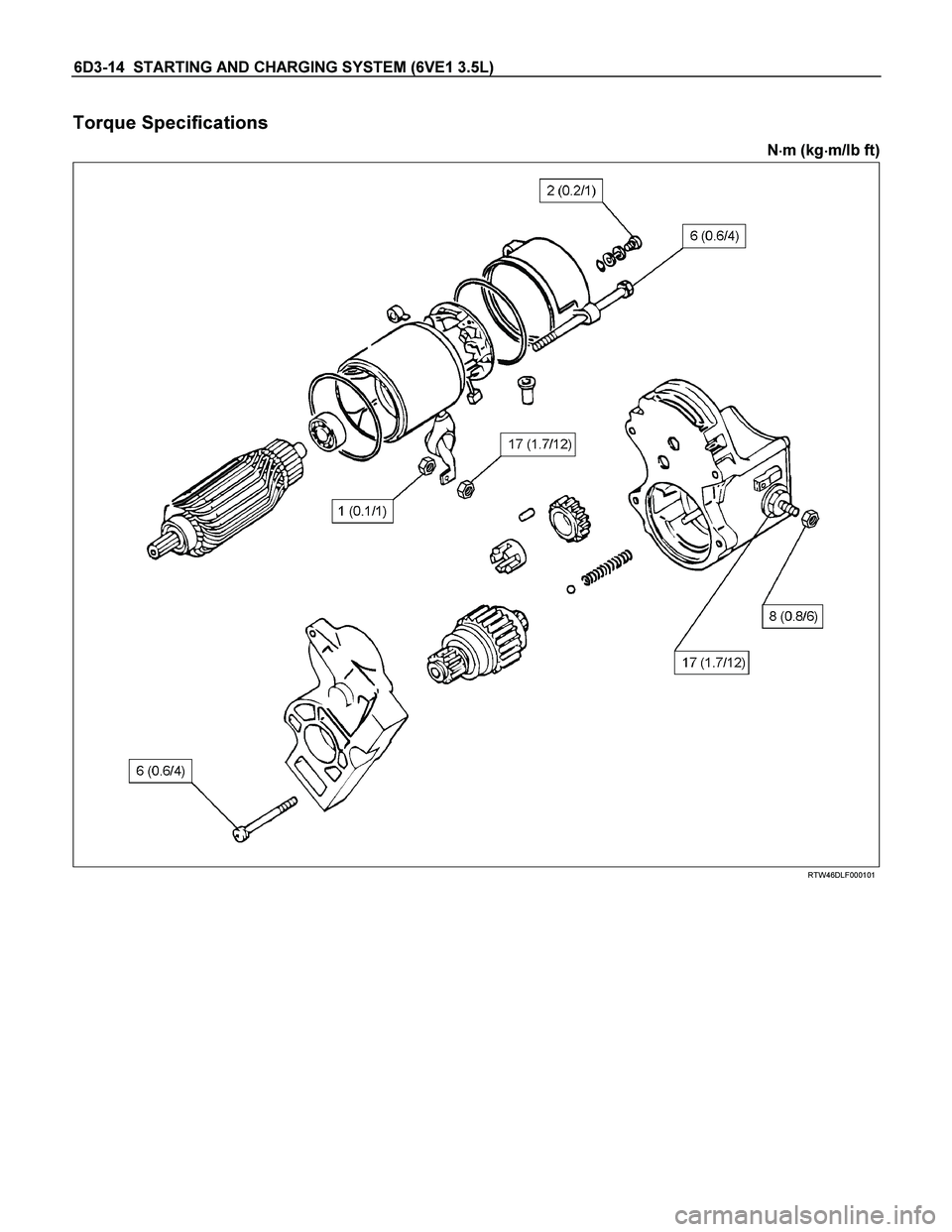
6D3-14 STARTING AND CHARGING SYSTEM (6VE1 3.5L)
Torque Specifications
N�
�� �m (kg�
�� �m/lb ft)
RTW46DLF000101
 6D2-5
Crankshaft Position Sensor
Removal
1. Disconnect battery ground cable
2. Wiring connector from crankshaft position sensor.
3. Remove crankshaft position sen")

Main Data and Specifications
General Specifications
Ignition System
Ignition Form Electronic Ignition System (El system) with Crankshaft position sensor
Spa")
 6D3-13
Main Data and Specifications
General Specifications
Model ADX4IH
Rating
Voltage 12 V
Output 1.4 Kw
Time 30 sec
Number of teeth of pinion")