Page 2568 of 4264

6D3-14 STARTING AND CHARGING SYSTEM
7. To remove the pulley, mount an 8mm Allen key in the vice
with the short end upwards, place a 24mm ring spanner on
the puley nut, position the internal hexagon of the roto
r
shaft onto the Allen ken, loosen the nut and remove the
pulley.
Note: the pulley has an integral boss which locks up against
the bearing,
therefore no thrust collar is provided.
8. Removing the rotor assembly. Remove the four retaining
screws from the drive end housing, withdraw the roto
r
complete with the bearing.
Note: the rotor must not be pressed from the drive end housing
using a press as the bearing retaining plate and drive end
housing will be damaged or distorted. Parts removed in this
way must be replaced if the integrity of the generator is to be
maintained.
9. Remove the drive end bearing from the rotor shaft using a
chuck type puler, take care not to distort the fan assembl
y
during this process.
10. Remove the slipring end bearing using the same meghod
as in 9.
Clean
Thoroughly clean all components except the rotor and stator
with an approved cleaning agent. Ensure that all traced of oil
and dirt are removed. If an abrasive cleaner is used to remove
scale and paint from the housings take care not to abrade the
bearing and mounting spigot surfaces. The rotor and stator
must be cleaned with compressed air only, the use of solvents
could cause damage to the insulating materials.
Inspection
1. Rectifier assembly
The following test equipment is required.
The recitifier assembly is not repairable and must be replaced
if a faulty diode is detected during inspection.
(a)
Adiode tester where the DC output at the test probes does
not exceed 14 volts or in the case of AC testers 12 volts
RMS. This is to ensue that when inspection rectifiers fitted
with zener power diodes the forward and reverse checks
are completer and are not masked by the diode turning on
due to the zener breakdown voltage.
(b) A zenere diode tester with a DC output in excess of 30
volts, the tester should also incorporate internal curren
t
limiting set to 5 Ma. to prevent high currents during
inspection.
(c) Diodes can be destroyed during service due to high
temperature and overload, open circuits are usually a resul
t
of excessive voltage.
Page 2569 of 4264

STARTING AND CHARGING SYSTEM 6D3-15
Positive heatsink 8 diode 6 diode
H
G
Negative heatsink C
B
A
StarpointFEB+Bolt D Diode connections
Stator connection
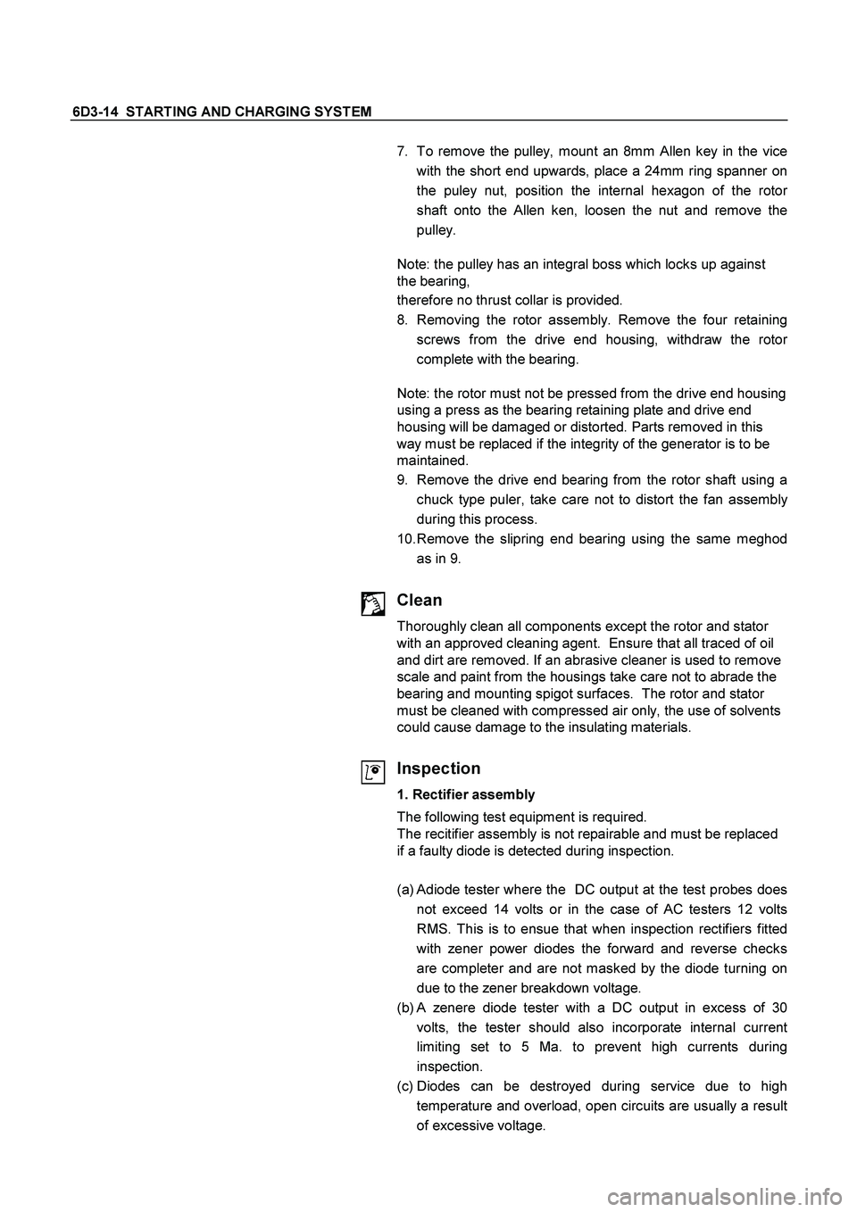
1.1 Power Diodes.
Apply the negative test probe of the diode tester or a
multimeter with a diode test feature to the positive heatsink
and the positive probe alternatevely to A,B,C, a low resistance
reading, or the forward voltage drop across the diode shoud be
obtained. Reverse the test probes, a high resistance reading or
a higher reverse voltage should be obtained.
Now connect the positive test probe to the negative heatsink
and the negative alternatively to D,E,F, a low resistance or
forward voltage drop across the diode should be obtained.
Reverse the test probes, a high resistance reading or a higher
reverse voltage should be obtained.
For 8 diode rectifier plates tests for G and H should be
included. When the reverse voltage test is done the applied
voltage should be less than 14 volts DC or 12 volts RMS for
AC testers.
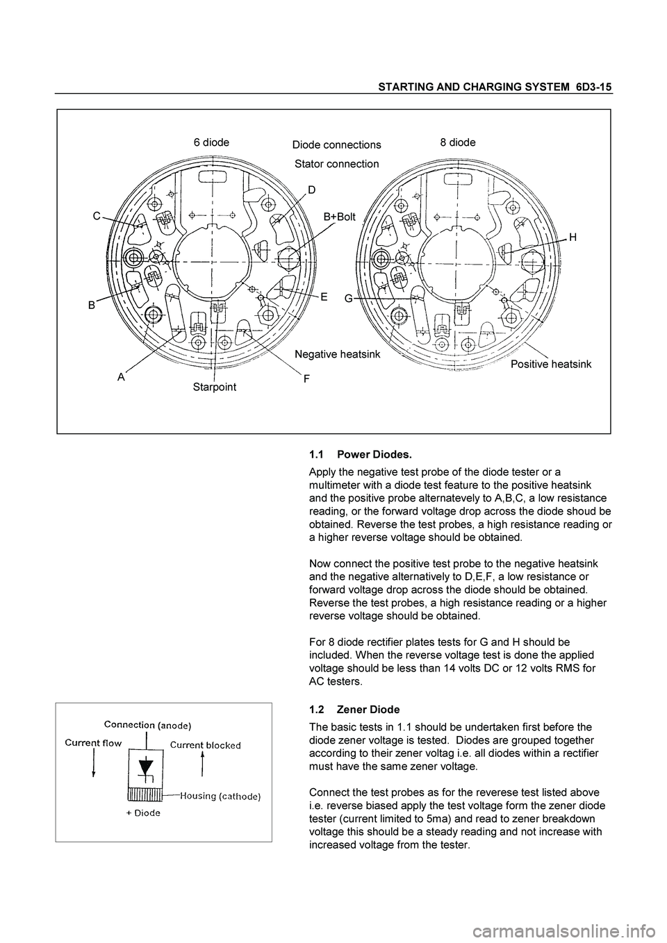
1.2 Zener Diode
The basic tests in 1.1 should be undertaken first before the
diode zener voltage is tested. Diodes are grouped together
according to their zener voltag i.e. all diodes within a rectifier
must have the same zener voltage.
Connect the test probes as for the reverese test listed above
i.e. reverse biased apply the test voltage form the zener diode
tester (current limited to 5ma) and read to zener breakdown
voltage this should be a steady reading and not increase with
increased voltage from the tester.
Page 2571 of 4264

STARTING AND CHARGING SYSTEM 6D3-17
fan.
4. Replacing the brushes (inbuilt regulator)
Check the brushes for length, this is measured from the brush
holder to the end of the brush along it's centre line. Also
inspect for any sideways wear. If worn replace both brushes.
The minimum length is 3.8mm. Inspect the brush springs for
signs of corrosion or loss of tension or uneven tension.
Replacing the brushes, using a soldering iron apply heat to the
soldered joints on the rear of the brush holder of the regulator,
using a small lever prise up the retaining tabs to release the
brush lead and spring. Thread the new brush lead up the
brush holder along with the spring, pull the lead through the
tabs until the brush is protruding 12mm from the holder.
Bend down the tabs and solder the brush lead taking care not
to allow the solder to run up the lead which will reduce
flexibility. Use 60/40 resin cored solder.
5. Ball bearing
Please note the bearings used in this KCA generator are a
high
tolerance type, only fully sealed bearings of the same
specification are to be used as replacements. It is
recommended that the bearings be replaced during the
reconditioning process to restore the unit to original
specification.
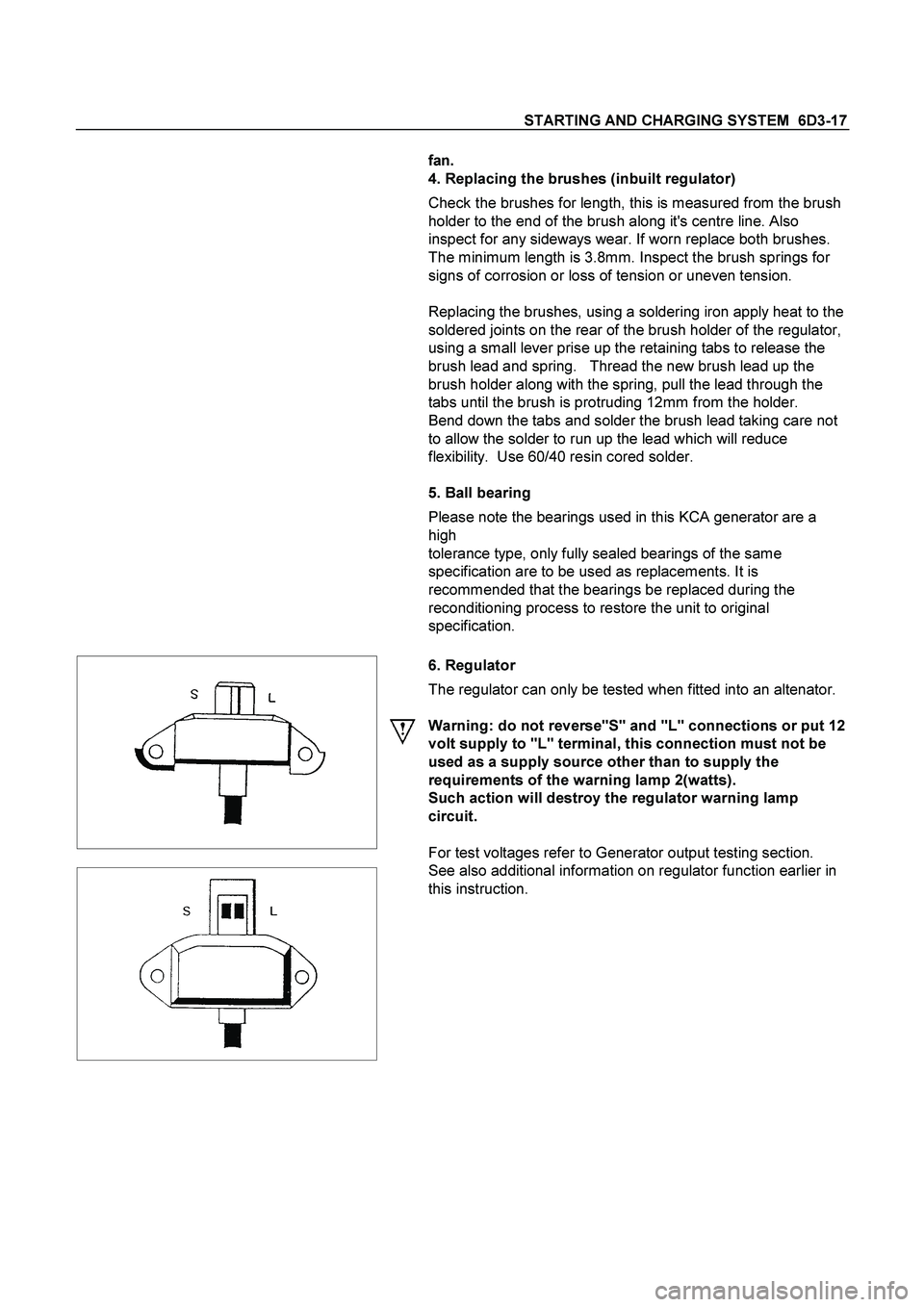
6. Regulator
The regulator can only be tested when fitted into an altenator.
Warning: do not reverse"S" and "L" connections or put 12
volt supply to "L" terminal, this connection must not be
used as a supply source other than to supply the
requirements of the warning lamp 2(watts).
Such action will destroy the regulator warning lamp
circuit.
For test voltages refer to Generator output testing section.
See also additional information on regulator function earlier in
this instruction.
Page 2862 of 4264
6F-6 ENGINE EXHAUST
Installation
To install, follow the removal steps in the reverse order.
Important - Installation
1. Front Exhaust Pipe Flange Nut
Connect the exhaust pipe to the exhaust manifold.
Front exhaust pipe to manifold nut.
Torque
N�m (kgf�m)
28 (2.9)
Inspection
Make the necessary adjustments, and part replacements if
excessive wear or damage is discover during inspection.
1. Front Exhaust Pipe
2. Center Exhaust Pipe and Catalytic Converter Flange Nut
3. Exhaust Pipe Damper Rubber
4. Exhaust Silencer with Rear Exhaust Pipe
Check the pipes for for corrosion, cracking , damage or
misalignment and repair if required.
Check the damper rubber for deterioration or damage and
repair if required.
Page 2879 of 4264
ENGINE LUBRICATION 6G-7
Inspection and Repair
CAUTION: Make necessary correction or parts replacement if wear, damage or any other
abnormal conditions are found through
inspection.
Reassembly
To install, follows the disassembly steps in the reverse order.
Important
Sealer - Apply silicon into groove in oil pan lugs prior to fitment of oil pan to block, remove excess sealer after oil pan
is bolted to block.
(2.4L 4 ×4 Model)
4
3
1
2
(2.4L 4 ×2 Model)
4
3
1
2
Torque
Bolts - Tighten bolts to the specified torque.
Torque : 20 N �m (2.0 kgf �m)
Engine oil - Refill engine oil to the oil pan. (Lit)
Replacement Oil Fill Volume 2.4L
Without filter change 4.00
With filter change 4.25
Page 3120 of 4264
7B-2 MSG MODEL
MAIN DATA AND SPECIFICATIONS
Transmission type Fully synchronized 5-forward gears with a constant
mesh type reverse gear.
Transmission Control Direct control with the gear shift lever on the floor.
Gear ratio MSG5K
1st : 4.122
2nd : 2.493
3rd : 1.504
4th : 1.000
5th : 0.855
Rev : 3.720
Oil capacity lit. (US gal.) 1.55(0.41)
Weight ; approx. kg(lbs) 33.3(73.8)
Page 3121 of 4264
MSG MODEL 7B-3
GENERAL DESCRIPTION
The MSG type transmission is fully synchronized 5-speed unit with blocking ring type synchronizers and a constant
mesh type reverse gear.
The unit consists principally of a case with an integral clutch housing, intermediate plate, rear cover and gears.
The top of the rear cover is a quadrant box containing the transmission control mechanism.
The case and rear cover are cast aluminum alloy to reduce weight.
Page 3129 of 4264

MSG MODEL 7B-11
Important Operations - Installation
Follow the removal procedure in the reverse order to perform
the installation procedure.
Pay careful attention to the important points during the
installation procedure.
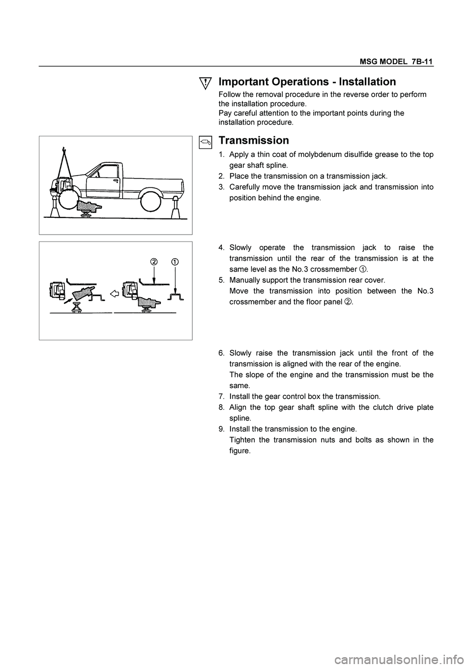
Transmission
1. Apply a thin coat of molybdenum disulfide grease to the top
gear shaft spline.
2. Place the transmission on a transmission jack.
3. Carefully move the transmission jack and transmission into
position behind the engine.
4. Slowly operate the transmission jack to raise the
transmission until the rear of the transmission is at the
same level as the No.3 crossmember
1 .
5. Manually support the transmission rear cover.
Move the transmission into position between the No.3
crossmember and the floor panel
2 .
6. Slowly raise the transmission jack until the front of the
transmission is aligned with the rear of the engine.
The slope of the engine and the transmission must be the
same.
7. Install the gear control box the transmission.
8. Align the top gear shaft spline with the clutch drive plate
spline.
9. Install the transmission to the engine.
Tighten the transmission nuts and bolts as shown in the
figure.