Page 921 of 4264
ELECTRICAL-BODY AND CHASSIS 8A-263
WARNING LIGHT BULB, INDICATOR
LIGHT BULB AND ILLUMINATION LIGHT
BULB
Removal
Turn the bulb socket counterclockwise and pull the bulb out.
Installation
To Install, follow the removal steps in the reverse order.
FUEL TANK UNIT
Removal
Dismount the fuel tank first, then remove the fuel tank unit.
1. Remove the rear inner liner -LH
� Remove the clip
2. Remove the filler neck.
� Remove the screw
3. Remove the ground with cable.
4. Remove the fuel tank band.
� T/M jack unit on the vehicle.
� Disconnect fuel line quick connectors.
5. Remove the fuel tank unit from the fuel tank.
Page 922 of 4264
8A-264 ELECTRICAL-BODY AND CHASSIS
Installation
Rubber Seal
Be absolutely sure that the fuel tank unit rubber seal is
correctly seated.
Connector
Be absolutely sure that the fuel tank unit connector is securely
connected.
This will prevent a poor contact and an open circuit.
VEHICLE SPEED SENSOR (INSTALLED
ON THE TRANSMISSION)
Removal
1. Disconnect the connector.
2. Remove the vehicle speed sensor body by rotating it.
Installation
To Install, follow the removal steps in the reverse order, noting
the following point.
Tighten the vehicle speed sensor to the specified torque.
Vehicle Speed Sensor Tightening Torque N�m (kgf�m/lb.ft)
25 � 4.9 (2.5 � 0.5/18 � 3.6)
Page 963 of 4264
ELECTRICAL-BODY AND CHASSIS 8A-305
REMOVAL AND INSTALLATION
This photo is based on 2 doors
DRIVER SEAT SIDE POWER WINDOW &
DOOR LOCK SWITCH
Removal
1. Disconnect the battery ground cable.
2. Removes the screw in pull cup with the screwdriver.
3. Remove the switch bezel by pushing the spring with the tip
of a screwdriver.
4. Disconnect the connector.
ATTENTION:
When removing a switch bezel lift from the front in the
bezel.
It follows the front with the screwdriver.
The clip has broken when lifting from the rear in the bezel.
Installation
To install, follow the removal steps in the reverse order.
DRIVER’S SIDE DOOR LOCK SWITCH
Removal
1. Door Lock ASM
� Refer to the removal steps of the DOORS in section 10
“BODY”.
2. Door Lock Switch
Installation
To install, follow the removal steps in the reverse order.
Page 964 of 4264
8A-306 ELECTRICAL-BODY AND CHASSIS
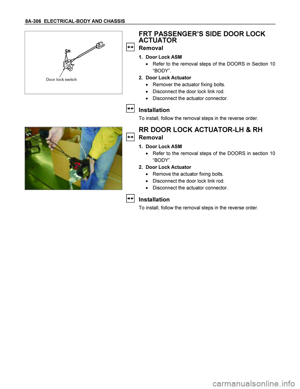
FRT PASSENGER’S SIDE DOOR LOCK
ACTUATOR
Removal
1. Door Lock ASM
� Refer to the removal steps of the DOORS in Section 10
“BODY”.
2. Door Lock Actuator
� Remover the actuator fixing bolts.
� Disconnect the door lock link rod.
� Disconnect the actuator connector.
Installation
To install, follow the removal steps in the reverse order.
RR DOOR LOCK ACTUATOR-LH & RH
Removal
1. Door Lock ASM
� Refer to the removal steps of the DOORS in section 10
“BODY”.
2. Door Lock Actuator
� Remove the actuator fixing bolts.
� Disconnect the door lock link rod.
� Disconnect the actuator connector.
Installation
To install, follow the removal steps in the reverse order.
Page 977 of 4264

Removal
1. Disconnect t")
ELECTRICAL-BODY AND CHASSIS 8A-319
REMOVAL AND INSTALLATION
This photo is based on RHD
DRIVER SEAT SIDE POWER WINDOW &
DOOR LOCK SWITCH
(2 DOORS MODEL)
Removal
1. Disconnect the battery ground cable.
2. Removes the screw in pull cup with the tip of a screwdriver.
3. Remove the switch bezel by pushing the spring with the tip
of a screwdriver.
4. Disconnect the connector.
ATTENTION:
When removing a switch bezel lift from the front in the
bezel.
It follows the front with the screwdriver.
The clip has broken when lifting from the rear in the bezel.
Installation
To install, follow the removal steps in the reverse order.
This photo is based on RHD
FRONT PASSENGER’S POWER WINDOW
& DOOR LOCK SWITCH
(2 DOORS MODEL)
Removal
1. Disconnect the battery ground cable.
2. Removes the screw in pull cup with the tip of a screwdriver.
3. Remove the switch bezel by pushing the spring with the tip
of a screwdriver.
4. Disconnect the connector.
ATTENTION:
When removing a switch bezel lift from the front in the
bezel.
It follows the front with the screwdriver.
The clip has broken when lifting from the rear in the bezel.
Installation
To install, follow the removal steps in the reverse order.
Page 978 of 4264

Removal
1. Disconnect the battery ground cable.
2. Removes the")
8A-320 ELECTRICAL-BODY AND CHASSIS
This photo is based on RHD
DRIVER SEAT SIDE POWER WINDOW &
DOOR LOCK SWITCH
(4 DOORS MODEL)
Removal
1. Disconnect the battery ground cable.
2. Removes the screw in pull cup with the tip of a screwdriver.
3. Remove the switch bezel by pushing the spring with the tip
of a screwdriver.
4. Disconnect the connector.
ATTENTION:
When removing a switch bezel lift from the front in the
bezel.
It follows the front with the screwdriver.
The clip has broken when lifting from the rear in the bezel.
Installation
To install, follow the removal steps in the reverse order.
This photo is based on RHD
FRONT PASSENGER’S POWER WINDOW
& DOOR LOCK SWITCH
(4 DOORS MODEL)
Removal
1. Disconnect the battery ground cable.
2. Removes the screw in pull cup with the tip of a screwdriver.
3. Remove the switch bezel by pushing the spring with the tip
of a screwdriver.
4. Disconnect the connector.
ATTENTION:
When removing a switch bezel lift from the front in the
bezel.
It follows the front with the screwdriver.
The clip has broken when lifting from the rear in the bezel.
Installation
To install, follow the removal steps in the reverse order.
REAR POWER WINDOW & DOOR LOCK
SWITCH-LH & RH
Removal
1. Disconnect the battery ground cable.
2. Removes the screw in pull cup with the tip of a screwdriver.
3. Remove the switch bezel by pushing the spring with the tip
of a screwdriver.
4. Disconnect the connector.
ATTENTION:
When removing a switch bezel lift from the front in the
bezel.
It follows the front with the screwdriver.
The clip has broken when lifting from the rear in the bezel.
Page 979 of 4264
ELECTRICAL-BODY AND CHASSIS 8A-321
Installation
To install, follow the removal steps in the reverse order.
Page 980 of 4264
8A-322 ELECTRICAL-BODY AND CHASSIS
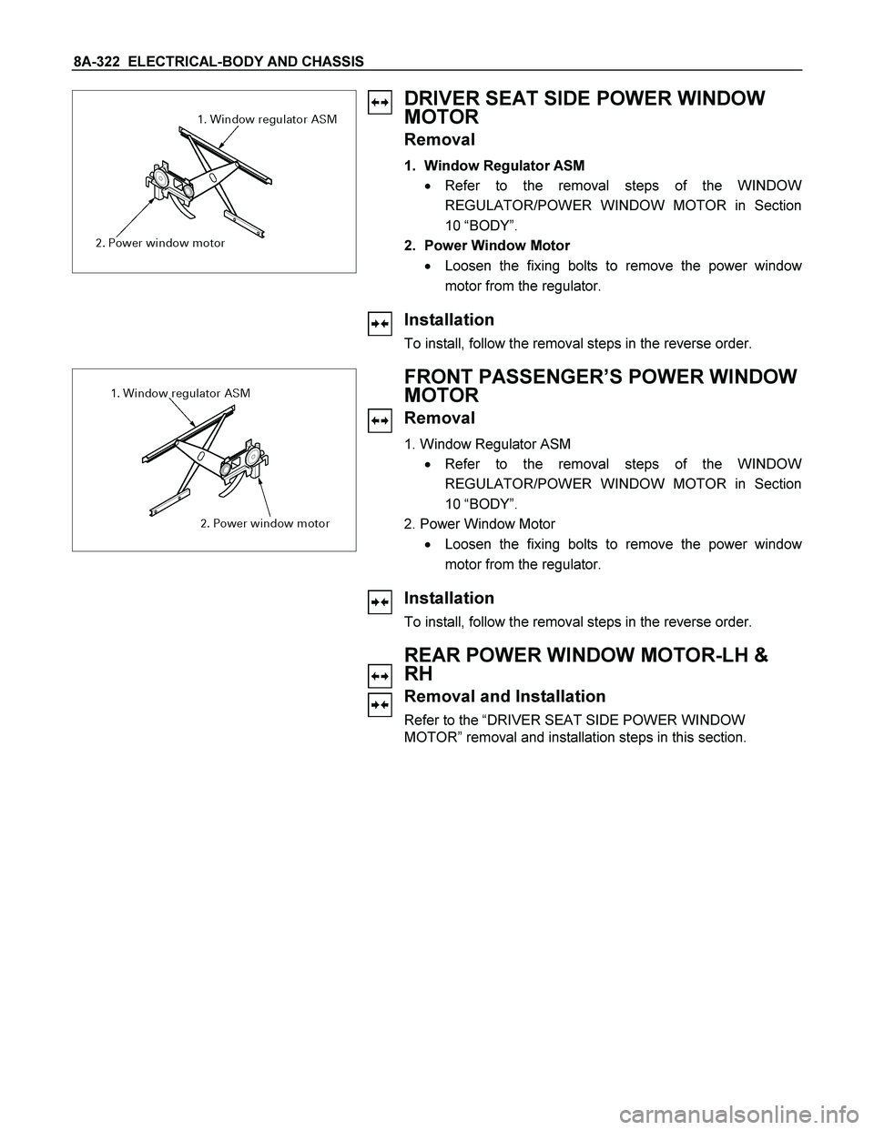
DRIVER SEAT SIDE POWER WINDOW
MOTOR
Removal
1. Window Regulator ASM
� Refer to the removal steps of the WINDOW
REGULATOR/POWER WINDOW MOTOR in Section
10 “BODY”.
2. Power Window Motor
� Loosen the fixing bolts to remove the power windo
w
motor from the regulator.
Installation
To install, follow the removal steps in the reverse order.
FRONT PASSENGER’S POWER WINDOW
MOTOR
Removal
1. Window Regulator ASM
� Refer to the removal steps of the WINDOW
REGULATOR/POWER WINDOW MOTOR in Section
10 “BODY”.
2. Power Window Motor
� Loosen the fixing bolts to remove the power windo
w
motor from the regulator.
Installation
To install, follow the removal steps in the reverse order.
REAR POWER WINDOW MOTOR-LH &
RH
Removal and Installation
Refer to the “DRIVER SEAT SIDE POWER WINDOW
MOTOR” removal and installation steps in this section.