Page 1106 of 4264
8B-8 CRUISE CONTROL SYSTEM
Cruise Control Unit
RTW3A0SH001101
Removal
1. Disconnect the battery ground cable.
2. Remove the dash side trim panel (LH) (1).
3. Disconnect the connector.
4. Remove a fixing nut to remove the cruise control unit (2).
Installation
To install, follow the removal steps in the reverse order.
Cruise Actuator
Actuator Cable Diagram
RTW3A0SF000301
Legend
(1) Cruise Actuator Assembly
(2) Cruise Control Cable
(3) Accelerator Cable
(4) Throttle Link (Cruise Control Side)
Page 1107 of 4264
CRUISE CONTROL SYSTEM 8B-9
RTW3A0SH001001
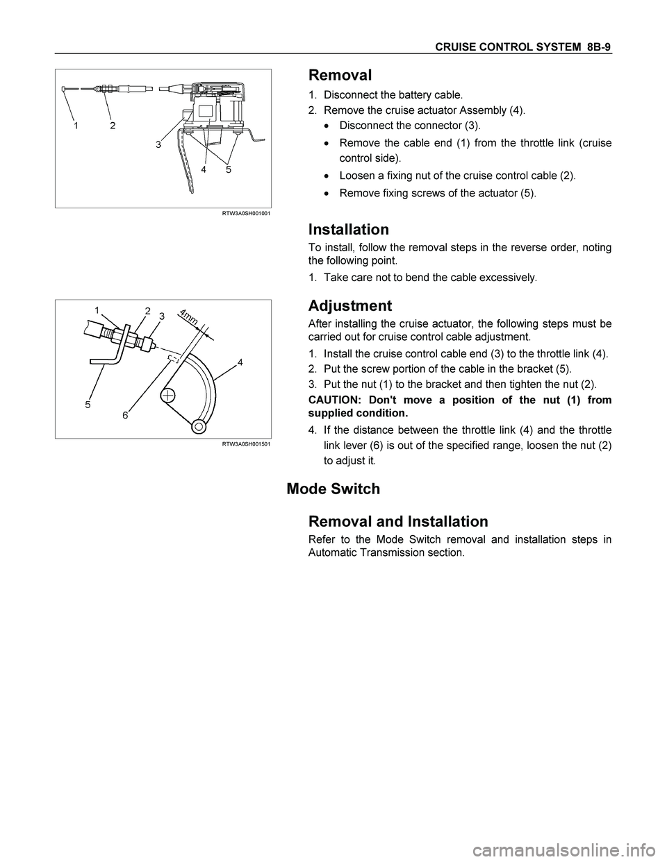
Removal
1. Disconnect the battery cable.
2. Remove the cruise actuator Assembly (4).
� Disconnect the connector (3).
� Remove the cable end (1) from the throttle link (cruise
control side).
� Loosen a fixing nut of the cruise control cable (2).
� Remove fixing screws of the actuator (5).
Installation
To install, follow the removal steps in the reverse order, noting
the following point.
1. Take care not to bend the cable excessively.
RTW3A0SH001501
Adjustment
After installing the cruise actuator, the following steps must be
carried out for cruise control cable adjustment.
1. Install the cruise control cable end (3) to the throttle link (4).
2. Put the screw portion of the cable in the bracket (5).
3. Put the nut (1) to the bracket and then tighten the nut (2).
CAUTION: Don't move a position of the nut (1) from
supplied condition.
4. If the distance between the throttle link (4) and the throttle
link lever (6) is out of the specified range, loosen the nut (2)
to adjust it.
Mode Switch
Removal and Installation
Refer to the Mode Switch removal and installation steps in
Automatic Transmission section.
Page 1180 of 4264
6A – 40 ENGINE MECHANICAL
140R300001
26. Fuel Hose
Remove the fuel hose from the fuel filter (Except EURO
III).
RTW46ASH000501
Remove the fuel hose from injection pump (EURO III
only).
27. Exhaust Pipe
Remove the front exhaust pipe bolts and separate the
exhaust manifold and the front exhaust pipe.
28. Engine Assembly
1) Remove two right side engine foot bolts.
2) Remove two left side engine mount bolts.
3) Use the hoist to lift the engine from the engine
compartment.
Installation
To reassemble, follow the removal steps in the reverse
order.
022R300002
F06R300008
Page 1345 of 4264
ENGINE ELECTRICAL 6D – 7
GENERATOR
REMOVAL AND INSTALLATION
Read this Section carefully before performing any removal and installation procedure. This Section gives you
important points as well as the order of operation. Be sure that you understand everything in this Section before you
begin.
P1010002
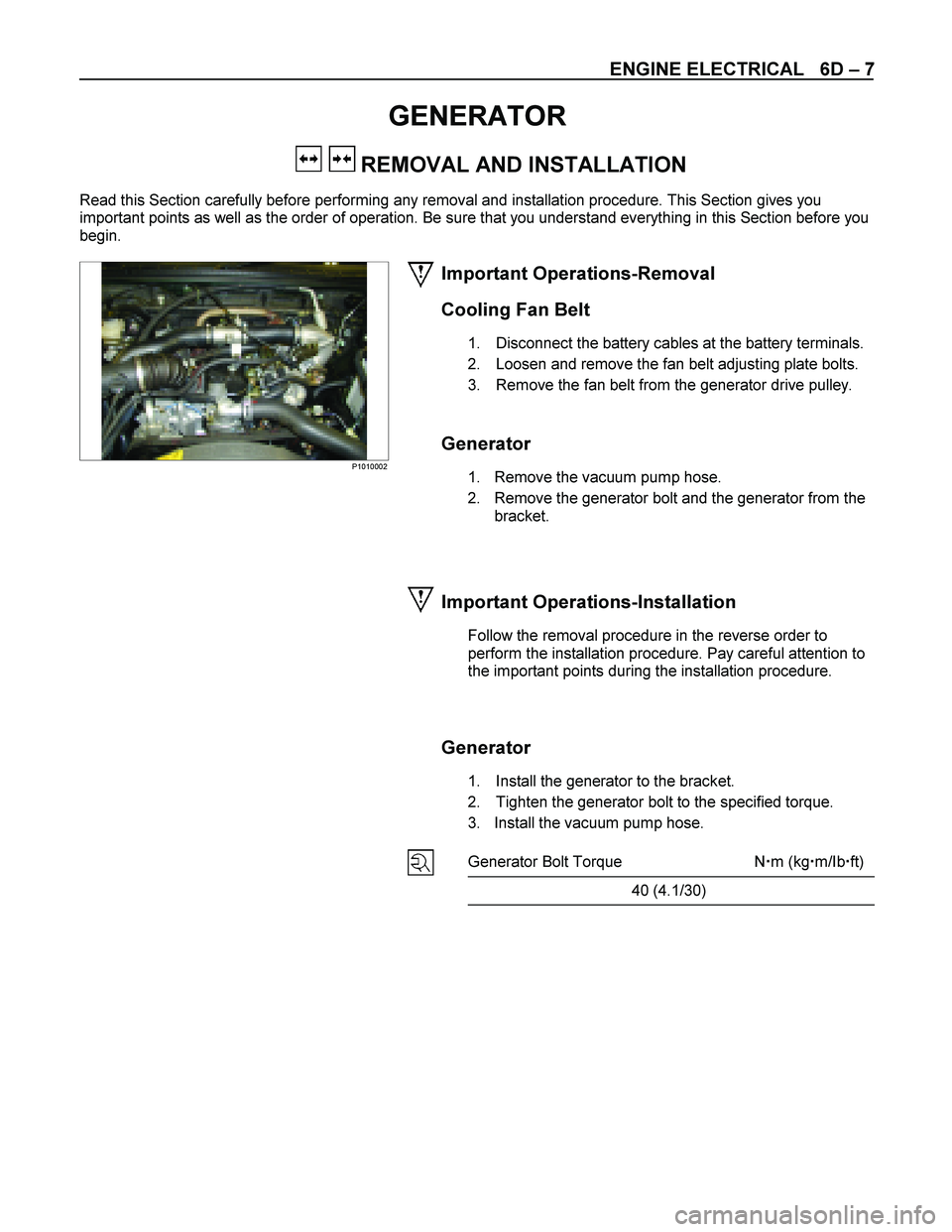
Important Operations-Removal
Cooling Fan Belt
1. Disconnect the battery cables at the battery terminals.
2. Loosen and remove the fan belt adjusting plate bolts.
3. Remove the fan belt from the generator drive pulley.
Generator
1. Remove the vacuum pump hose.
2. Remove the generator bolt and the generator from the bracket.
Important Operations-Installation
Follow the removal procedure in the reverse order to
perform the installation procedure. Pay careful attention to
the important points during the installation procedure.
Generator
1. Install the generator to the bracket.
2. Tighten the generator bolt to the specified torque.
3. Install the vacuum pump hose.
Generator Bolt Torque N �m (kg �m/Ib �ft)
40 (4.1/30)
Page 1360 of 4264
6D – 22 ENGINE ELECTRICAL
STARTER MOTOR
REMOVAL AND INSTALLATION
Read this Section carefully before performing any removal and installation procedure. This Section gives you
important points as well as the order of operation. Be sure that you understand everything in this Section before you
begin.
Important Operations - Removal
Starter Motor
1. Disconnect the battery cable and the ground cable at the battery terminals.
2. Disconnect the magnetic switch cable at the terminal bolts.
3. Disconnect the battery cable at the starter motor and the ground cable at the cylinder body.
4. Remove the starter motor from the engine.
Important Operations – Installation
Follow the removal procedure in the reverse order to
perform the installation procedure. Pay careful attention to
the important points during the installation procedure.
Starter Motor
1. Install the starter motor to the rear plate.
2. Tighten the starter motor bolts to the specified torque.
Starter Motor Bolt Torque N �m (kg �m/lb �ft)
85 (8.7/63)
3. Reconnect the battery cable at the starter motor and
the ground cable at the cylinder body.
4. Reconnect the battery cable and the ground cable at the battery terminals.
Page 1799 of 4264
EXHAUST SYSTEM 6F – 5
Important Operations – Installation
Follow the removal procedure in the reverse order to
perform the installation procedure. Pay careful attention to
the important points during the installation procedure.
1. Front Pipe Nut
Connect the exhaust pipe to the catalytic converter.
Torque N�m (kg�m/lb�ft)
67 (6.8/49)
2. Middle pipe Nut (4�
�� �4 only)
Connect the middle pipe to the front pipe.
Torque N�m (kg�m/lb�ft)
43 (4.4/32)
3. Silencer Front Nut
Connect the silencer to the front or middle pipe.
Torque N�m (kg�m/lb�ft)
43 (4.4/32)
Page 1962 of 4264
6D1-4 ENGINE ELECTRICAL (6VE1 3.5L)
Jump Starting Procedure
1. Set the vehicle parking brake.
If the vehicle is equipped with an automatic
transmission, place the selector level in the “PARK"
position.
If the vehicle is equipped with a manual
transmission, place the shift lever in the
“ NEUTRAL" position.
Turn “OFF" the ignition.
Turn “OFF" all lights and any other accessory
requiring electrical power.
2. Look at the built –in hydrometer.
If the indication area of the built –in hydrometer is
completely clear, do not try to jump start.
3.
Attach the end of one jumper cable to the positive
terminal of the booster battery.
Attach the other end of the same cable to the
positive terminal of the discharged battery.
Do not allow the vehicles to touch each other. This
will cause a ground connection, effectively
neutralizing the charging procedure.
Be sure that the booster battery has a 12 volt rating.
4. Attach one end of the remaining cable to the
negative terminal of the booster battery.
Attach the other end of the same cable to a solid
engine ground (such as the air conditioning
compressor bracket or the generator mounting
bracket) of the vehicle with the discharged battery.
The ground connection must be at least 450 mm
(18 in.) from the battery of the vehicle whose battery
is being charged.
WARNING: NEVER ATTACH THE END OF THE
JUMPER CABLE DIRECTLY TO THE NEGATIVE
TERMINAL OF THE DEAD BATTERY.
5. Start the engine of the vehicle with the good battery.
Make sure that all unnecessary electrical
accessories have been turned “OFF".
6. Start the engine of the vehicle with the dead battery.
7. To remove the jumper cables, follow the above directions in reverse order.
Be sure to first disconnect the negative cable from
the vehicle with the discharged battery.
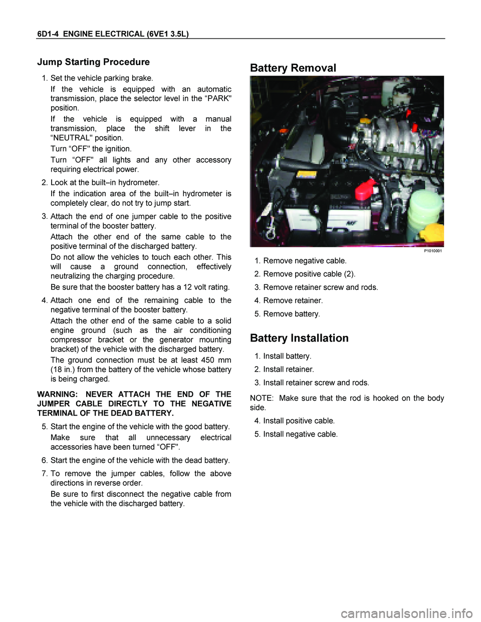
Battery Removal
P1010001
1. Remove negative cable.
2. Remove positive cable (2).
3. Remove retainer screw and rods.
4. Remove retainer.
5. Remove battery.
Battery Installation
1. Install battery.
2. Install retainer.
3. Install retainer screw and rods.
NOTE: Make sure that the rod is hooked on the body
side.
4. Install positive cable.
5. Install negative cable.
Page 1966 of 4264
6D2-2 IGNITION SYSTEM (6VE1 3.5L)
General Description
Ignition is done by the electronic ignition (El) that directly
fires the spark plugs from ignition coils through spark
plug wires without using a distributor. A pair of ignition
coils for the cylinders having different phases by 360�
(No.1 and No.4, No.2 and No.5, No.3 and No.6) are
fired simultaneously.
Since the cylinder on exhaust stroke requires less
energy to fire its ignition plug, energy from the ignition
coils can be utilized to fire the mating cylinder on
compression stroke. After additional 360�rotation,
respective cylinder strokes are reversed.
The EI consists of six ignition coils, crankshaft position
sensor, engine control module (ECM) and othe
r
components.
The ignition coils are connected with the ECM.
The ECM turns on/off the primary circuit of ignition coils,
and also it controls the ignition timing.
A notch in the timing disc on the crankshaft activates
the crankshaft position sensor which then sends
information such as firing order and starting timing o
f
each ignition coil to the ECM.
Further, the El employs ignition control (IC) to control
similar to a distributor system.
Diagnosis
Refer to Section Drivability and Emissions for the
diagnosis to electronic ignition system (El system).