Page 642 of 4264
7C-40 CLUTCH
REASSEMBLY
To reassemble, follow the disassembly steps in the reverse order, noting the following points:
206RS006
1. Before installing the parts, apply a thin coat of rubber
grease.
2. Install cup in groove in piston with the lip turned to the fron
t
of cylinder. Use care so as not to scratch the cylinder.
Page 663 of 4264

ELECTRICAL-BODY AND CHASSIS 8A-5
NOTES FOR WORKING ON ELECTRICAL ITEMS
Battery
BATTERY CABLE
Disconnecting the Battery Cable
1. All switches should be "OFF" position.
2. Disconnect the battery ground cable.
3. Disconnect the battery positive cable.
CAUTION:
It is important that the battery ground cable be
disconnected first.
Disconnecting the battery positive cable first can result in
a short circuit.
Connecting the Battery Cable
Follow the disconnecting procedure in the reverse order to
connect the battery cables.
CAUTION:
Clean the battery terminal and apply light coat of grease to
prevent terminal corrosion.
CONNECTOR HANDLING
Disconnecting the Connectors
Some connectors have a tang lock to hold the connectors
together during vehicle operation.
Some tang locks are released by pulling them towards you
1.
Other tang locks are released by pressing them forward
2.
Determine which type of tang lock is on the connector being
handled.
Firmly grasp both sides (male and female) of the connector.
Release the tang lock and carefully pull the two halves of the
connector apart.
Never pull on the wires to separate the connectors.
This will result in wire breakage.
Page 675 of 4264
ELECTRICAL-BODY AND CHASSIS 8A-17
DIODE
Diode Specifications and Configurations
SHAPE
MARK/
COLOR
CONSTRUCTION CHECKING
THERE SHOULD BE CONTINUITY IN
EITHER A OR B WHEN A CIRCUIT
TESTER IS CONNECTED WITH
DIODE TERMINAL
BLACK
21
CONNECTION A+-
PATTERN B-+
TERMINAL NO.
BLACK
321
-+
CONNECTION+-
PATTERN+-
-+B A TERMINAL NO.
BLACK
321
-+
CONNECTION+-
PATTERN+-
-+B A TERMINAL NO.
BLACK
4321
+-
A-+
CONNECTION-+
PATTERN-+
B+-
+-
TERMINAL NO.
Maximum Rating (Temp.=25�
�� �C)
Items Rating Remarks
Peak reverse voltage 400V
Transient peak reverse voltage 500V
Average output current 1.5A Temp.=40�C
Working ambient temperature -30�C�80�C
Storage temperature -40�C�100ßC
Page 679 of 4264
ELECTRICAL-BODY AND CHASSIS 8A-21
Caution:
Do not attach the booster cable to the discharged battery
negative terminal.
11. Start the engine of the vehicle with the booster battery.
Check that all unnecessary electrical accessories are off.
12. Start the engine of the vehicle with the discharged battery.
13. Remove the jumper cables in the reverse order to which
they were attached.
Caution:
Be absolutely sure to remove the negative jumper cable
from the vehicle with the discharged battery first.
Page 746 of 4264
8A-88 ELECTRICAL-BODY AND CHASSIS
REMOVAL AND INSTALLATION
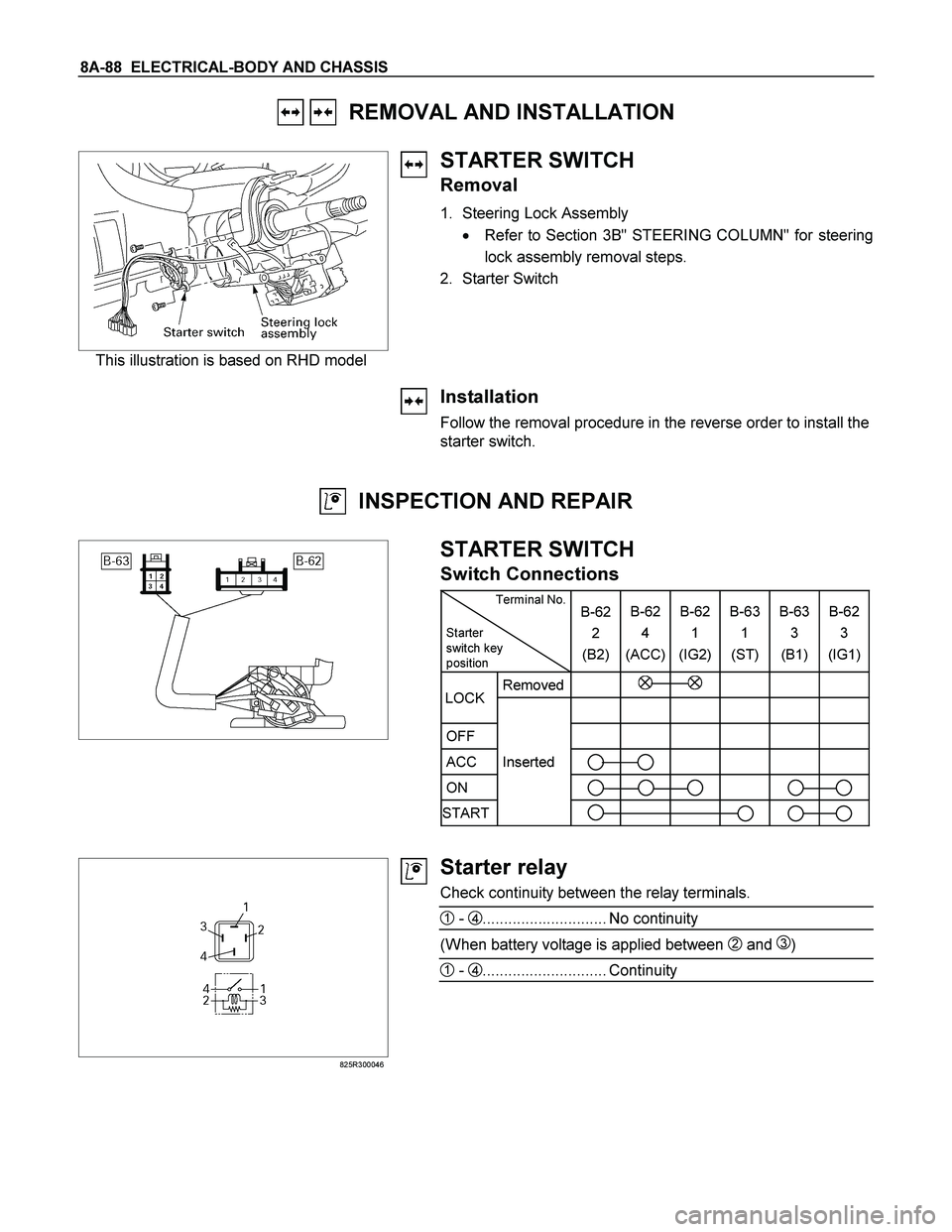
This illustration is based on RHD model
STARTER SWITCH
Removal
1. Steering Lock Assembly
� Refer to Section 3B" STEERING COLUMN" for steering
lock assembly removal steps.
2. Starter Switch
Installation
Follow the removal procedure in the reverse order to install the
starter switch.
INSPECTION AND REPAIR
STARTER SWITCH
Switch Connections
Terminal No.
Starter
switch key
position B-62
2
(B2)B-62
4
(ACC)B-62
1
(IG2) B-63
1
(ST) B-63
3
(B1)B-62
3
(IG1)
Removed
OFF
ACC Inserted
ON
START
LOCK
825R300046
Starter relay
Check continuity between the relay terminals.
1 - 4............................. No continuity
(When battery voltage is applied between 2 and 3)
1 - 4............................. Continuity
Page 763 of 4264
ELECTRICAL-BODY AND CHASSIS 8A-105
REMOVAL AND INSTALLATION
ECM (ENGINE CONTROL MODULE):
C24SE
Removal
1. Lift both the ECM harness connector locking levers and
remove the two harness connectors form the ECM.
2. Remove the four socket head screws securing the ECM to
the mounting bracket.
3. Remove the ECM from the engine compartment
.
4. Pull out the ECM.
5. Disconnect both red and tan connectors.
Refer to the Section 6E-ENGINE of this Manual.
IMPORTANT: The replacement ECM must be programmed.
“SPS (Service Programming System) and immobiliser
programming (if equipped) is/are necessary”
Installation
Follow the removal procedure in the reverse order to install the
ECM.
Pay close attention to the important points mentioned in the
following paragraphs.
Connector
Be absolutely sure that ECM is securely connected.
This will prevent a poor contact and open circuit.
Page 764 of 4264
8A-106 ELECTRICAL-BODY AND CHASSIS
REMOVAL AND INSTALLATION
ECM (ENGINE CONTROL MODULE):
6VE1
Removal
1. Pull both the red ECM harness connector locks toward the
front of the vehicle, and remove the two harness connectors
form the ECM.
2. Remove the four hex-head screws securing the ECM to the
common chamber.
3. Remove the ECM from the engine compartment.
4. Pull out the ECM.
5. Disconnect both red and tan connectors.
Refer to the Section 6E-ENGINE of this Manual.
IMPORTANT: The replacement ECM must be programmed.
“SPS (Service Programming System) and immobiliser
programming (if equipped) is/are necessary”
Installation
Follow the removal procedure in the reverse order to install the
ECM.
Pay close attention to the important points mentioned in the
following paragraphs.
Connector
Be absolutely sure that ECM is securely connected.
This will prevent a poor contact and open circuit.
Page 765 of 4264
:
4JA1-TC / 4JH1-TC
Removal
1. Remove the passenger side front seat – refer to Section 10
CA")
ELECTRICAL-BODY AND CHASSIS 8A-107
REMOVAL AND INSTALLATION
ECM (ENGINE CONTROL MODULE):
4JA1-TC / 4JH1-TC
Removal
1. Remove the passenger side front seat – refer to Section 10
CAB.
2. Remove the passenger side front door opening scuff plate.
3. Raise the carpet to gain access to the four hex-head bolts
securing the ECM and ECM cover to the floorpan
.
4. Remove the four hex-head bolts.
5. Pull the two harness connector locks away from the
harness connectors and then remove the connectors form
the ECM.
6. Remove the ECM from the vehicle.
Refer to the Section 6E-ENGINE of this Manual.
IMPORTANT: The replacement ECM must be programmed.
“SPS (Service Programming System) and immobiliser
programming (if equipped) is/are necessary”
Installation
Follow the removal procedure in the reverse order to install the
ECM.
Torque passenger seat securing bolts to the specified value –
refer to Section 10 CAB
Pay close attention to the important points mentioned in the
following paragraphs.
Connector
Be absolutely sure that ECM is securely connected.
This will prevent a poor contact and open circuit.


:
C24SE
Removal
1. Lift both the ECM harness connector locking levers and
remove the two harness")
:
6VE1
Removal
1. Pull both the red ECM harness connector locks toward the
front of the vehicle, an")