Page 146 of 4264

4A-10 PROPELLER SHAFT
Diagnosis of Propeller Shaft and
Universal Joint
Condition Possible cause Correction
Rough surface on splined yoke;
burred nicked or worn. Replace the seal. Minor burrs can
be Smoothed by careful use of
crocus cloth or fine stone honing.
Replace the yoke if badly burred. Leak at the Front Slip Yoke (An
Occasional Drop of Lubricant
Leaking from the Splined Yoke is
Normal)
Defective transmission rear oil seal. Replace the transmission rear oil
seal and replenish the transmission
oil.
Worn universal joint bearings. Replace.
Improper lubrication. Lubricate as directed.
Universal Joint Noise.
Loose flange bolts. Tighten to specifications.
Loose bushing bolts on the rear
springs or upper and lower control
arms. Tighten the bolts to specified
torque. Ping, Snap, or Click in Drive Line
(Usually Heard on Initial Load after
the Transmission is in Forward or
Reverse Gear)
Loose or out-of-phase end yoke. Remove end yoke, turn 180
degrees from its original position,
lubricate the splines and reinstall.
Tighten the bolts and pinion nut to
specified torque.
Squeak Lack of lubricant. Lubricate joints and splines. Also
check for worn or brinelled parts.
Loose or missing bolts at the
flanges. Replace or tighten bolts to specified
torque.
Incorrectly set front joint angle. Install shim under the transmission
support mount to change the front
joint angle.
Shudder on Acceleration (Low
Speed)
Worn universal joint. Replace.
Incorrect shaft runout. Replace.
Shaft out of balance. Adjust.
Transmission rear housing bushing,
transfer case housing bushing worn.Replace.
Vibration
Yoke spline jammed. Replace.
Page 276 of 4264
, then
loosen the nut to the full.
Tighten the hub nut at the value given below, using a s")
4C1-56 FRONT WHEEL DRIVE
Preload Adjustment
Tighten the hub nut at 29.4 N�m (3 kgf�m / 21.716 lb.ft), then
loosen the nut to the full.
Tighten the hub nut at the value given below, using a spring
scale on the wheel pin.
Bearing Preload N(lb)
New bearing and New oil seal 20 - 25 (4.4 - 5.5)
Used bearing and New oil seal 12 - 18 (2.68 - 4.0)
If the measured bearing preload is outside the specifications,
adjust it by loosening or tightening the bearing nut.
9. Lock Washer
Turn the side with larger diameter of the tapered bore to the
vehicle outer side, and attach the washer.
If the bolt holes in the lock plate are not aligned with the
corresponding holes in the nut, reverse the lock plate.
If the bolt holes are still out of alignment, turn in the nut just
enough to obtain alignment,. Screw is to be fastened tightly so
its head may come lower than the surface of the washer.
11. Snap ring, shims (4
�
�� �4 model only)
Adjust the clearance between the flange and the snap ring.
Clearance mm(in)
0 - 0.2 (0 - 0.08)
Adjust shims available
mm(in)
0.2, 0.3, 0.5, 1.0
(0.008, 0.011, 0.020, 0.039)
RTW440SH000901
13.
Bolt
Torque N�m (kgf�m/lb�ft
)
59 (6.0 / 43)
Page 285 of 4264
, then
loosen the nut to the full.
Tighten the hub nut at the value given below, using a s")
FRONT WHEEL DRIVE 4C1-65
Preload Adjustment
Tighten the hub nut at 29.4 N�m (3 kgf�m / 21.716 lb.ft), then
loosen the nut to the full.
Tighten the hub nut at the value given below, using a spring
scale on the wheel pin.
Bearing Preload N(lb)
New bearing and New oil seal 20 - 25 (4.4 - 5.5)
Used bearing and New oil seal 12 - 18 (2.68 - 4.0)
If the measured bearing preload is outside the specifications,
adjust it by loosening or tightening the bearing nut.
21. Lock Washer
Turn the side with larger diameter of the tapered bore to the
vehicle outer side, and attach the washer.
If the bolt holes in the lock plate are not aligned with the
corresponding holes in the nut, reverse the lock plate.
If the bolt holes are still out of alignment, turn in the nut just
enough to obtain alignment,. Screw is to be fastened tightly so
its head may come lower than the surface of the washer.
22. Body Assembly
Apply adhesive (Loctite 15 or equivalent) to the both joining
faces.
23. Snap Ring and Shims
Adjust the clearance between the free wheeling hub body and
the snap ring.
Clearance mm(in)
0 - 0.2 (0 - 0.08)
Adjust Shims Available mm(in)
0.2, 0.3, 0.5, 1.0
(0.008, 0.011, 0.020, 0.039)
24. Cover Assembly
Align stopper nails to grooves of body.
Page 302 of 4264
4C2-4 SHIFT ON THE FLY SYSTEM
Shift On The Fly System and Association Parts
RTW440LF000701
Disassembly steps
1. Filler plug
2. Bolt
3. Front axle drive shaft (LH side)
4. Bolt
5. Actuator assembly
6. Bolt
7. Housing
8. Sleeve
9. Clutch gear
10. Snap ring
11. Inner shaft
12. Snap ring
13. Inner shaft bearing
14. Needing bearing
15. Oil seal
Reassembly steps
To reassemble, follow the disassembly steps in
the reverse order.
Page 477 of 4264
BRAKES 5C-51
BRAKE CONTROL
REMOVAL AND INSTALLATION
BRAKE PEDAL ASSEMBLY
This illustration shows RHD model
LHD model is opposite.
310R300001
Removal Steps
1. Nut ; fulcrum pin
2. Pin ; fulcrum, pedal to bracket
3. Pedal arm
4. Return spring
5. Pedal pad
Installation steps
To install, follow the removal procedure in
reverse order.
Before installation, apply grease to the entire
circumference of the fulcrum pin (2).
Refer to "SERVICING" in this section for
adjustment procedure of brake pedal.
Page 577 of 4264
CAB 10-69
Important Operation - Installation
1. Fuel Filler Lid Cable Assembly
�
Install the cable holder of cable assembly to the recess
and push the grommet in to the back panel. Fix the clips
to the pointed places.
Note:
To install, follow the removal steps in the reverse order,
noting the following points.
�
�� � Do not make extreme curve on the cable.
�
�� � Install the cable from inside of the cab.
Page 623 of 4264
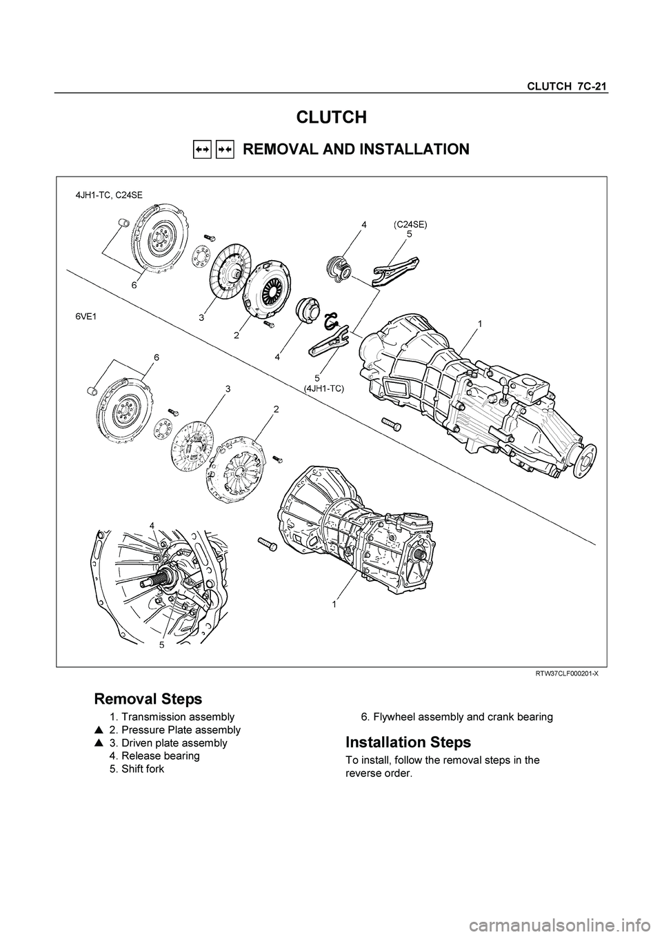
CLUTCH 7C-21
CLUTCH
REMOVAL AND INSTALLATION
RTW37CLF000201-X
Removal Steps
1. Transmission assembly
�
2. Pressure Plate assembly
�
3. Driven plate assembly
4. Release bearing
5. Shift fork
6. Flywheel assembly and crank bearing
Installation Steps
To install, follow the removal steps in the
reverse order.
Page 625 of 4264
CLUTCH 7C-23
015RW053
6. Flywheel Assembly and Crank Bearing (6VE1)
(1) Remove flywheel assembly and crankshaft bearing. Do no
t
remove except for replacement.
(2) Use the remover 5-8840-2000-0 (J-5822) and sliding
hammer 5-8840-0019-0 (J-23907) to remove the crankshaf
t
bearing
Important Operations - Installation
Follow the removal procedure in reverse order to perform the
installation procedure.
Pay careful attention to the important points during the
installation procedure.
015RW054
6. Flywheel Assembly and Crank Bearing (6VE1)
(1) Install flywheel assembly and crankshaft bearing. Use the
installer 5-8840-0125-0 (J-26516-A) and driver handle 5-
8840-0007-0 (J-8092) to install the crankshaft bearing then
clean and lubricate with grease.
015RS047
(2) Install new flywheel fixing bolts in the order illustrated and
tighten them to the specified torque.
N�
m (kg�
m/lb ft)
6VE1 54 (5.5/40)
NOTE: Do not reuse the bolt and do not apply oil or thread lock
to the bolt.

4. Bolt")


(1) Remove flywheel assembly and crankshaft bearing. Do no
t
remove except for replacement.
(2) Use the remover 5-8840-2000-0")