Page 748 of 2234
140KP±01
A01155
A01156
A01159
Plastigage
A62797
Front
±
ENGINE MECHANICAL CYLINDER BLOCK (1ZZ±FE/3ZZ±FE)
14±39
1ZZ±FE,3ZZ±FE ENGINE REPAIR MANUAL
(RM923E)
OVERHAUL
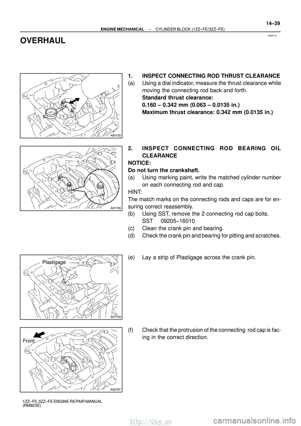
1. INSPECT CONNECTING ROD THRUST CLEARANCE
(a) Using a dial indicator, measure the thrust clearance while
moving the connecting rod back and forth.
Standard thrust clearance:
0.160 ± 0.342 mm (0.063 ± 0.0135 in.)
Maximum thrust clearance: 0.342 mm (0.0135 in.)
2. INSPECT CONNECTING ROD BEARING OIL CLEARANCE
NOTICE:
Do not turn the crankshaft.
(a) Using marking paint, write the matched cylinder number on each connecting rod and cap.
HINT:
The match marks on the connecting rods and caps are for en-
suring correct reassembly.
(b) Using SST, remove the 2 connecting rod cap bolts. SST 09205±16010
(c) Clean the crank pin and bearing.
(d) Check the crank pin and bearing for pitting and scratches.
(e) Lay a strip of Plastigage across the crank pin.
(f) Check that the protrusion of the connecting rod cap is fac- ing in the correct direction.
http://vnx.su
Page 749 of 2234
A01163
A62798
Paint Mark
90
�
Front
A01160
A62799
Mark
1, 2 or 3
A01166
14±40
±
ENGINE MECHANICAL CYLINDER BLOCK (1ZZ±FE/3ZZ±FE)
1ZZ±FE,3ZZ±FE ENGINE REPAIR MANUAL
(RM923E)
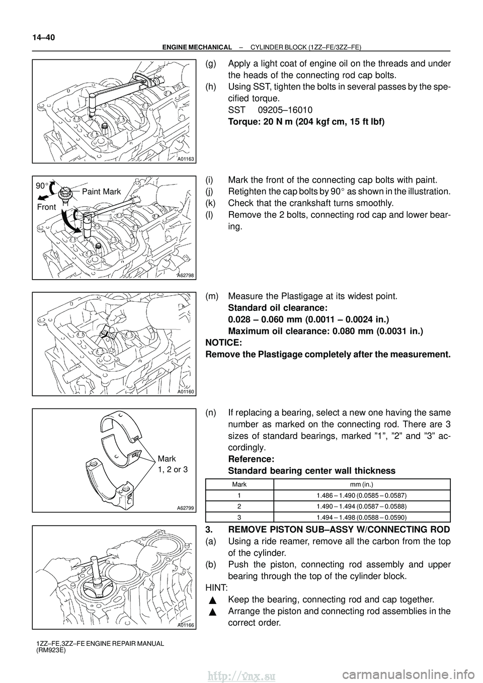
(g) Apply a light coat of engine oil on the threads and under the heads of the connecting rod cap bolts.
(h) Using SST, tighten the bolts in several passes by the spe-
cified torque.
SST 09205±16010
Torque: 20 N �m (204 kgf� cm, 15 ft�lbf)
(i) Mark the front of the connecting cap bolts with paint.
(j) Retighten the cap bolts by 90 � as shown in the illustration.
(k) Check that the crankshaft turns smoothly.
(l) Remove the 2 bolts, connecting rod cap and lower bear- ing.
(m) Measure the Plastigage at its widest point. Standard oil clearance:
0.028 ± 0.060 mm (0.0011 ± 0.0024 in.)
Maximum oil clearance: 0.080 mm (0.0031 in.)
NOTICE:
Remove the Plastigage completely after the measurement.
(n) If replacing a bearing, select a new one having the same
number as marked on the connecting rod. There are 3
sizes of standard bearings, marked º1º, º2º and º3º ac\
-
cordingly.
Reference:
Standard bearing center wall thickness
Markmm (in.)
11.486 ± 1.490 (0.0585 ± 0.0587)
21.490 ± 1.494 (0.0587 ± 0.0588)
31.494 ± 1.498 (0.0588 ± 0.0590)
3. REMOVE PISTON SUB±ASSY W/CONNECTING ROD
(a) Using a ride reamer, remove all the carbon from the topof the cylinder.
(b) Push the piston, connecting rod assembly and upper
bearing through the top of the cylinder block.
HINT:
�Keep the bearing, connecting rod and cap together.
�Arrange the piston and connecting rod assemblies in the
correct order.
http://vnx.su
Page 753 of 2234
A62804
A62805
A01171
A01170
14±44
±
ENGINE MECHANICAL CYLINDER BLOCK (1ZZ±FE/3ZZ±FE)
1ZZ±FE,3ZZ±FE ENGINE REPAIR MANUAL
(RM923E)
18. INSPECT PISTON OIL CLEARANCE
(a) Subtract the piston diameter measurement from the cylinder bore diameter\
measurement. Standard oil clearance:
1ZZ±FE 0.065 ± 0.088 mm (0.0026 ± 0.0035 in.)
3ZZ±FE 0.035 ± 0.058 mm (0.0014 ± 0.0023 in.)
Maximum oil clearance:
1ZZ±FE 0.088 mm (0.0035 in.)
3ZZ±FE 0.058 mm (0.0023 in.)
If the oil clearance is greater than maximum, replace all the 4 pistons. I\
f necessary, replace the cylinder block.
19. INSPECT CONNECTING ROD SUB±ASSY
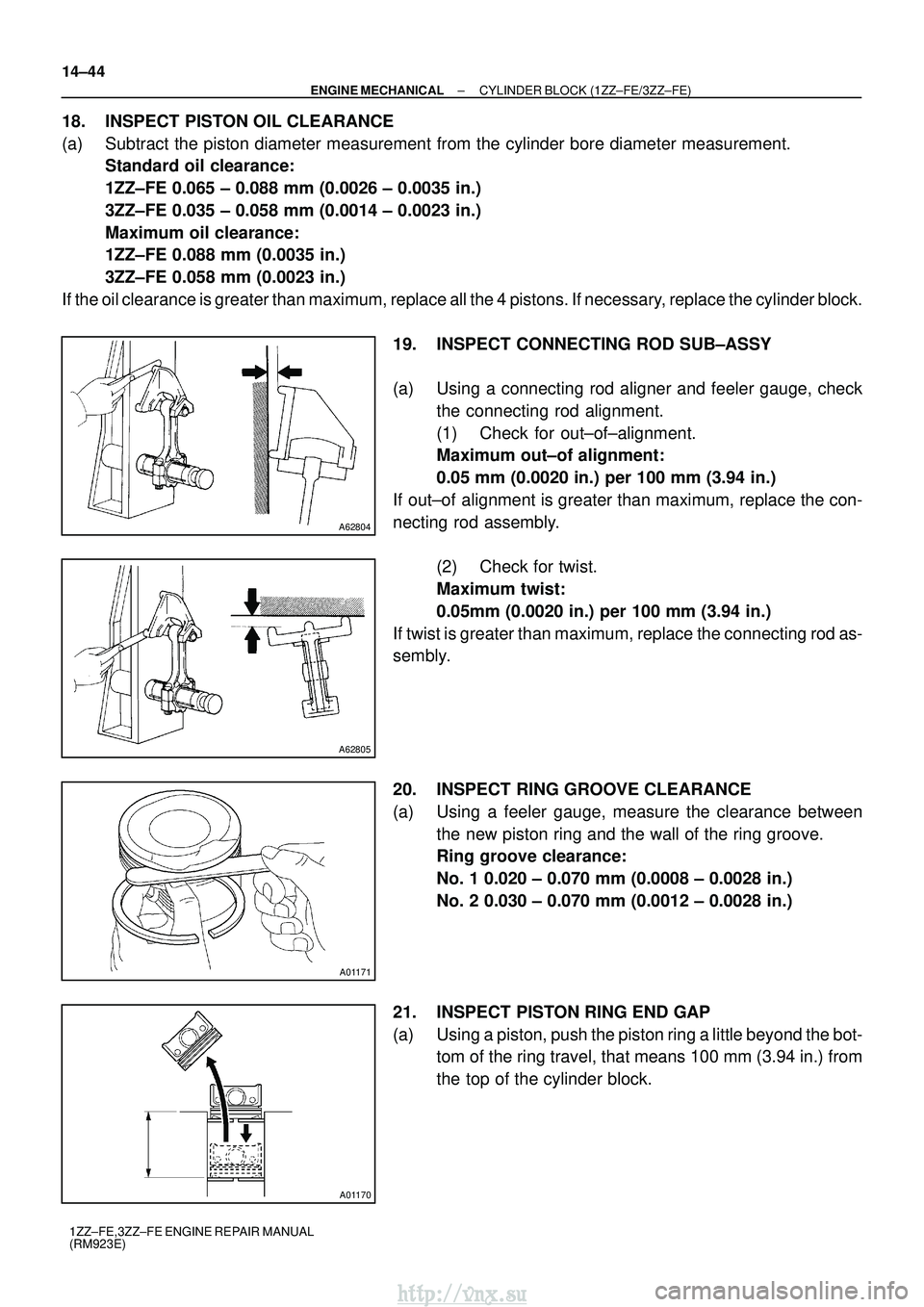
(a) Using a connecting rod aligner and feeler gauge, checkthe connecting rod alignment.
(1) Check for out±of±alignment.
Maximum out±of alignment:
0.05 mm (0.0020 in.) per 100 mm (3.94 in.)
If out±of alignment is greater than maximum, replace the con-
necting rod assembly.
(2) Check for twist.
Maximum twist:
0.05mm (0.0020 in.) per 100 mm (3.94 in.)
If twist is greater than maximum, replace the connecting rod as-
sembly.
20. INSPECT RING GROOVE CLEARANCE
(a) Using a feeler gauge, measure the clearance between the new piston ring and the wall of the ring groove.
Ring groove clearance:
No. 1 0.020 ± 0.070 mm (0.0008 ± 0.0028 in.)
No. 2 0.030 ± 0.070 mm (0.0012 ± 0.0028 in.)
21. INSPECT PISTON RING END GAP
(a) Using a piston, push the piston ring a little beyond the bot- tom of the ring travel, that means 100 mm (3.94 in.) from
the top of the cylinder block.
http://vnx.su
Page 754 of 2234
EM7639
EM0227
A01470
A11783
ZF6927
±
ENGINE MECHANICAL CYLINDER BLOCK (1ZZ±FE/3ZZ±FE)
14±45
1ZZ±FE,3ZZ±FE ENGINE REPAIR MANUAL
(RM923E)
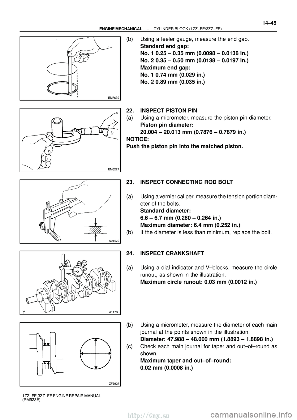
(b) Using a feeler gauge, measure the end gap.
Standard end gap:
No. 1 0.25 ± 0.35 mm (0.0098 ± 0.0138 in.)
No. 2 0.35 ± 0.50 mm (0.0138 ± 0.0197 in.)
Maximum end gap:
No. 1 0.74 mm (0.029 in.)
No. 2 0.89 mm (0.035 in.)
22. INSPECT PISTON PIN
(a) Using a micrometer, measure the piston pin diameter. Piston pin diameter:
20.004 ± 20.013 mm (0.7876 ± 0.7879 in.)
NOTICE:
Push the piston pin into the matched piston.
23. INSPECT CONNECTING ROD BOLT
(a) Using a vernier caliper, measure the tension portion diam- eter of the bolts.
Standard diameter:
6.6 ± 6.7 mm (0.260 ± 0.264 in.)
Maximum diameter: 6.4 mm (0.252 in.)
(b) If the diameter is less than minimum, replace the bolt.
24. INSPECT CRANKSHAFT
(a) Using a dial indicator and V±blocks, measure the circle runout, as shown in the illustration.
Maximum circle runout: 0.03 mm (0.0012 in.)
(b) Using a micrometer, measure the diameter of each main journal at the points shown in the illustration.
Diameter: 47.988 ± 48.000 mm (1.8893 ± 1.8898 in.)
(c) Check each main journal for taper and out±of±round as shown.
Maximum taper and out±of±round:
0.02 mm (0.0008 in.)
http://vnx.su
Page 755 of 2234
ZF6928
A01194
A11780
Plastigage
A62801
793
481062
15
A62806
Paint Mark
Front 90
�
14±46
±
ENGINE MECHANICAL CYLINDER BLOCK (1ZZ±FE/3ZZ±FE)
1ZZ±FE,3ZZ±FE ENGINE REPAIR MANUAL
(RM923E)
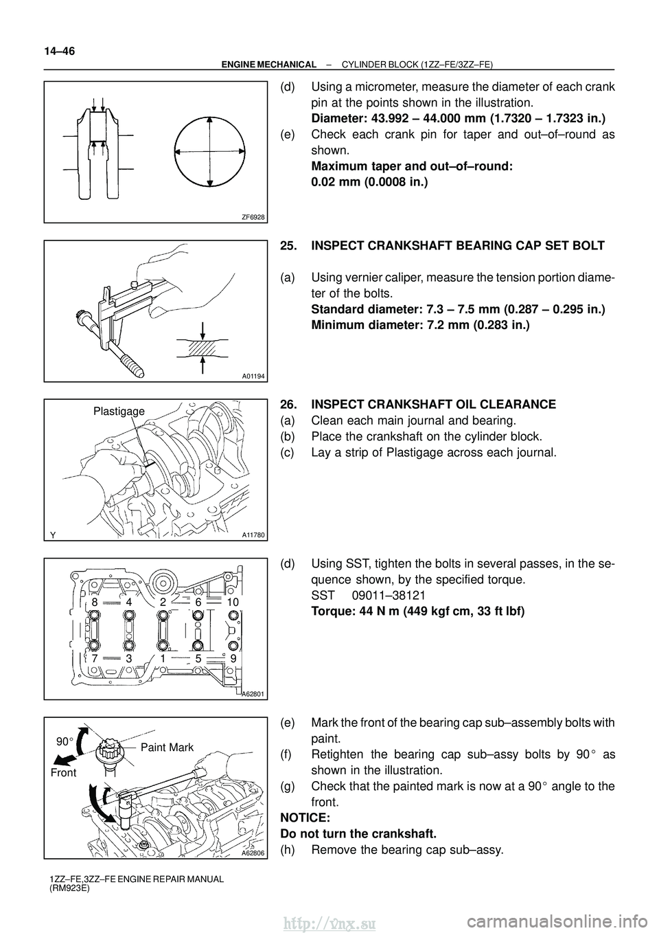
(d) Using a micrometer, measure the diameter of each crank pin at the points shown in the illustration.
Diameter: 43.992 ± 44.000 mm (1.7320 ± 1.7323 in.)
(e) Check each crank pin for taper and out±of±round as shown.
Maximum taper and out±of±round:
0.02 mm (0.0008 in.)
25. INSPECT CRANKSHAFT BEARING CAP SET BOLT
(a) Using vernier caliper, measure the tension portion diame- ter of the bolts.
Standard diameter: 7.3 ± 7.5 mm (0.287 ± 0.295 in.)
Minimum diameter: 7.2 mm (0.283 in.)
26. INSPECT CRANKSHAFT OIL CLEARANCE
(a) Clean each main journal and bearing.
(b) Place the crankshaft on the cylinder block.
(c) Lay a strip of Plastigage across each journal.
(d) Using SST, tighten the bolts in several passes, in the se- quence shown, by the specified torque.
SST 09011±38121
Torque: 44 N �m (449 kgf� cm, 33 ft�lbf)
(e) Mark the front of the bearing cap sub±assembly bolts with paint.
(f) Retighten the bearing cap sub±assy bolts by 90 � as
shown in the illustration.
(g) Check that the painted mark is now at a 90 � angle to the
front.
NOTICE:
Do not turn the crankshaft.
(h) Remove the bearing cap sub±assy.
http://vnx.su
Page 759 of 2234
A62800
SST
A36991
A01193
A62810
Front Mark
(Cavity)
(Protrusion)
A01192
14±50
±
ENGINE MECHANICAL CYLINDER BLOCK (1ZZ±FE/3ZZ±FE)
1ZZ±FE,3ZZ±FE ENGINE REPAIR MANUAL
(RM923E)
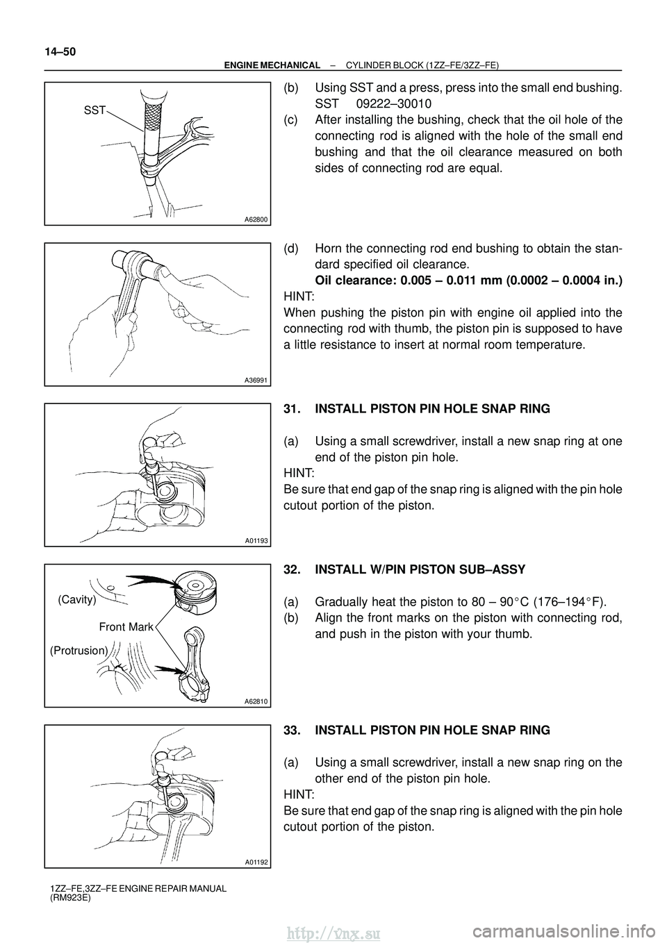
(b) Using SST and a press, press into the small end bushing. SST 09222±30010
(c) After installing the bushing, check that the oil hole of the
connecting rod is aligned with the hole of the small end
bushing and that the oil clearance measured on both
sides of connecting rod are equal.
(d) Horn the connecting rod end bushing to obtain the stan- dard specified oil clearance.
Oil clearance: 0.005 ± 0.011 mm (0.0002 ± 0.0004 in.)
HINT:
When pushing the piston pin with engine oil applied into the
connecting rod with thumb, the piston pin is supposed to have
a little resistance to insert at normal room temperature.
31. INSTALL PISTON PIN HOLE SNAP RING
(a) Using a small screwdriver, install a new snap ring at one end of the piston pin hole.
HINT:
Be sure that end gap of the snap ring is aligned with the pin hole
cutout portion of the piston.
32. INSTALL W/PIN PISTON SUB±ASSY
(a) Gradually heat the piston to 80 ± 90 �C (176±194� F).
(b) Align the front marks on the piston with connecting rod,
and push in the piston with your thumb.
33. INSTALL PISTON PIN HOLE SNAP RING
(a) Using a small screwdriver, install a new snap ring on the other end of the piston pin hole.
HINT:
Be sure that end gap of the snap ring is aligned with the pin hole
cutout portion of the piston.
http://vnx.su
Page 761 of 2234
A01191
A01038
Seal Packing
A62801
793
481062
15
A62806
Paint Mark
Front 90
�
14±52
±
ENGINE MECHANICAL CYLINDER BLOCK (1ZZ±FE/3ZZ±FE)
1ZZ±FE,3ZZ±FE ENGINE REPAIR MANUAL
(RM923E)
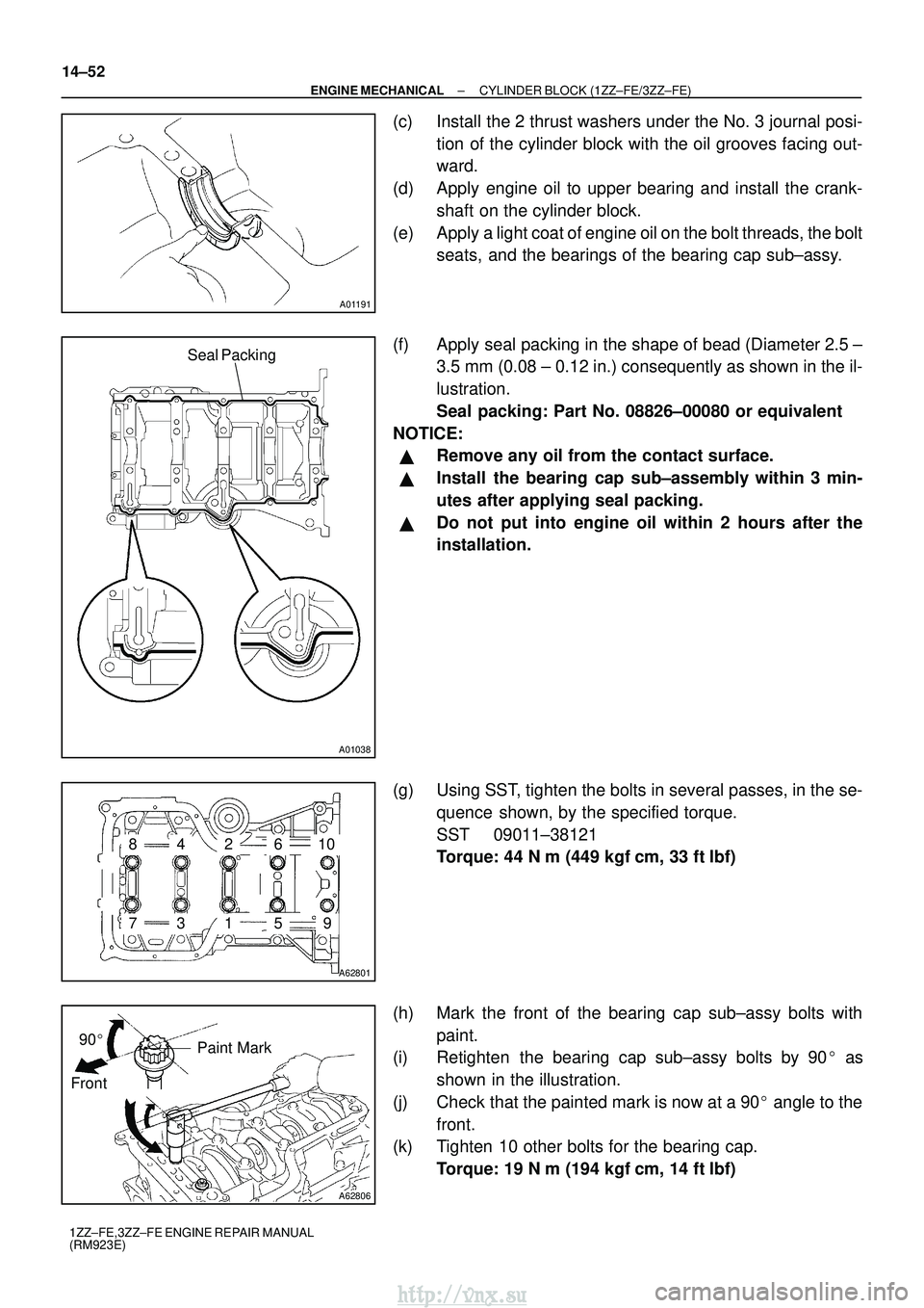
(c) Install the 2 thrust washers under the No. 3 journal posi- tion of the cylinder block with the oil grooves facing out-
ward.
(d) Apply engine oil to upper bearing and install the crank- shaft on the cylinder block.
(e) Apply a light coat of engine oil on the bolt threads, the bolt seats, and the bearings of the bearing cap sub±assy.
(f) Apply seal packing in the shape of bead (Diameter 2.5 ± 3.5 mm (0.08 ± 0.12 in.) consequently as shown in the il-
lustration.
Seal packing: Part No. 08826±00080 or equivalent
NOTICE:
�Remove any oil from the contact surface.
�Install the bearing cap sub±assembly within 3 min-
utes after applying seal packing.
�Do not put into engine oil within 2 hours after the
installation.
(g) Using SST, tighten the bolts in several passes, in the se- quence shown, by the specified torque.
SST 09011±38121
Torque: 44 N �m (449 kgf� cm, 33 ft�lbf)
(h) Mark the front of the bearing cap sub±assy bolts with paint.
(i) Retighten the bearing cap sub±assy bolts by 90 � as
shown in the illustration.
(j) Check that the painted mark is now at a 90 � angle to the
front.
(k) Tighten 10 other bolts for the bearing cap.
Torque: 19 N �m (194 kgf� cm, 14 ft�lbf)
http://vnx.su
Page 762 of 2234
A62813
Front Mark
A62797
Front
A01163
A62798
Paint Mark
90
�
Front
±
ENGINE MECHANICAL CYLINDER BLOCK (1ZZ±FE/3ZZ±FE)
14±53
1ZZ±FE,3ZZ±FE ENGINE REPAIR MANUAL
(RM923E)
37. INSTALL CONNECTING ROD SUB±ASSY
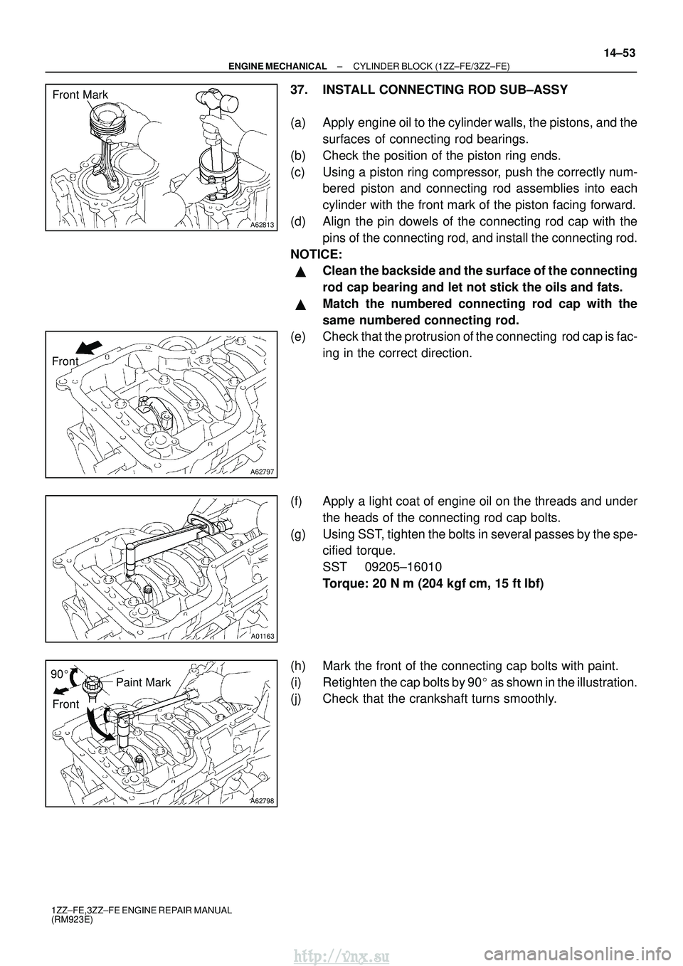
(a) Apply engine oil to the cylinder walls, the pistons, and the
surfaces of connecting rod bearings.
(b) Check the position of the piston ring ends.
(c) Using a piston ring compressor, push the correctly num- bered piston and connecting rod assemblies into each
cylinder with the front mark of the piston facing forward.
(d) Align the pin dowels of the connecting rod cap with the pins of the connecting rod, and install the connecting rod.
NOTICE:
�Clean the backside and the surface of the connecting
rod cap bearing and let not stick the oils and fats.
�Match the numbered connecting rod cap with the
same numbered connecting rod.
(e) Check that the protrusion of the connecting rod cap is fac-
ing in the correct direction.
(f) Apply a light coat of engine oil on the threads and under the heads of the connecting rod cap bolts.
(g) Using SST, tighten the bolts in several passes by the spe- cified torque.
SST 09205±16010
Torque: 20 N �m (204 kgf� cm, 15 ft�lbf)
(h) Mark the front of the connecting cap bolts with paint.
(i) Retighten the cap bolts by 90 � as shown in the illustration.
(j) Check that the crankshaft turns smoothly.
http://vnx.su