Page 841 of 2234
190AA±01
A62753
SST
1 ± BSST
1 ± A
A62754SST 2
A62755
SST
1 ± A
A62756
SST
1 ± A
SST
1 ± B
19±10
±
STARTING & CHARGING GENERATOR ASSY (1ZZ±FE/3ZZ±FE)
1ZZ±FE,3ZZ±FE ENGINE REPAIR MANUAL
(RM923E)
OVERHAUL
1. REMOVE GENERATOR PULLEY SST 09820±63010 (09820±06010, 09820±06020)
HINT:
SST1 ± A, B09820±06010
SST209820±06020
(a) Hold SST 1 ± A with a torque wrench, and tighten SST 1 ± B clockwise to the specified torque.
Torque: 39 N �m (398 kgf� cm, 29 ft�lbf)
NOTICE:
Check that SST is secured to the rotor shaft.
(b) Mount SST 2 in a vise.
(c) Insert SST 1 ± A, B into SST 2, and attach the pulley nut to SST 2.
(d) To loosen the pulley nut, turn SST 1 ± A in the direction shown in the illustration.
NOTICE:
To prevent damage to the rotor shaft, do not loosen the
pulley nut more than one±half of a turn.
(e) Remove the alternator form SST 2.
(f) Turn SST 1 ± B, and remove SST 1 ± A, B.
(g) Remove the pulley nut and pulley.
http://vnx.su
Page 842 of 2234

A62757
SST
A62881
FB
A62882
E F
±
STARTING & CHARGING GENERATOR ASSY (1ZZ±FE/3ZZ±FE)
19±11
1ZZ±FE,3ZZ±FE ENGINE REPAIR MANUAL
(RM923E)
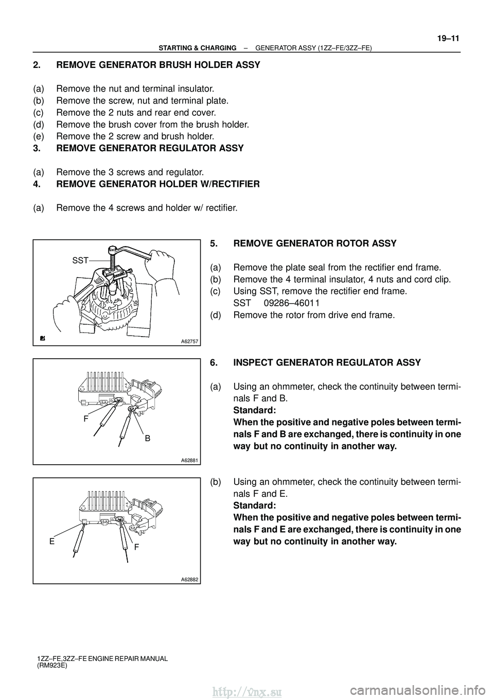
2. REMOVE GENERATOR BRUSH HOLDER ASSY
(a) Remove the nut and terminal insulator.
(b) Remove the screw, nut and terminal plate.
(c) Remove the 2 nuts and rear end cover.
(d) Remove the brush cover from the brush holder.
(e) Remove the 2 screw and brush holder.
3. REMOVE GENERATOR REGULATOR ASSY
(a) Remove the 3 screws and regulator.
4. REMOVE GENERATOR HOLDER W/RECTIFIER
(a) Remove the 4 screws and holder w/ rectifier.
5. REMOVE GENERATOR ROTOR ASSY
(a) Remove the plate seal from the rectifier end frame.
(b) Remove the 4 terminal insulator, 4 nuts and cord clip.
(c) Using SST, remove the rectifier end frame.SST 09286±46011
(d) Remove the rotor from drive end frame.
6. INSPECT GENERATOR REGULATOR ASSY
(a) Using an ohmmeter, check the continuity between termi- nals F and B.
Standard:
When the positive and negative poles between termi-
nals F and B are exchanged, there is continuity in one
way but no continuity in another way.
(b) Using an ohmmeter, check the continuity between termi- nals F and E.
Standard:
When the positive and negative poles between termi-
nals F and E are exchanged, there is continuity in one
way but no continuity in another way.
http://vnx.su
Page 843 of 2234

A62758
Slip Ring
A62759
Slip Ring
Rotor
A62760
A62761
B
P4
E
P2P1
B
P1 P2 P3P4
E
A62762
19±12
±
STARTING & CHARGING GENERATOR ASSY (1ZZ±FE/3ZZ±FE)
1ZZ±FE,3ZZ±FE ENGINE REPAIR MANUAL
(RM923E)
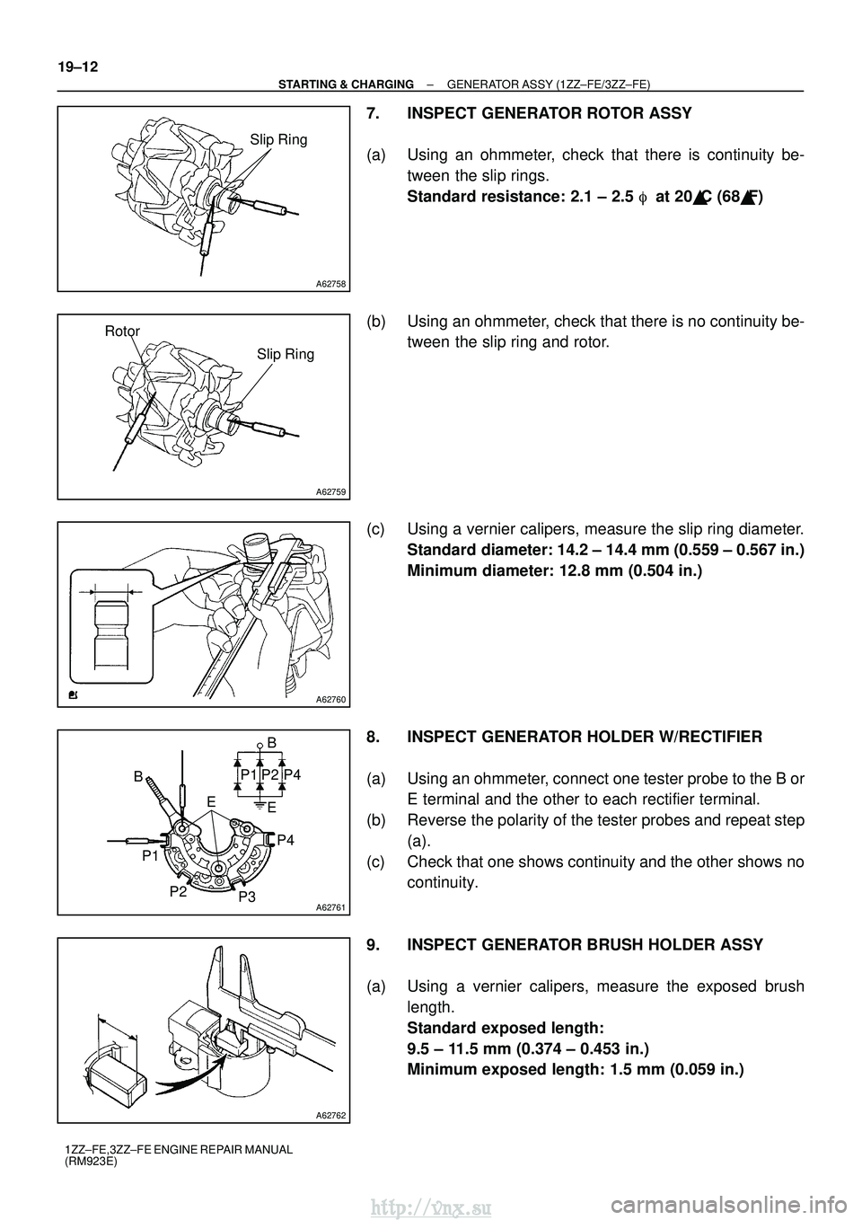
7. INSPECT GENERATOR ROTOR ASSY
(a) Using an ohmmeter, check that there is continuity be- tween the slip rings.
Standard resistance: 2.1 ± 2.5 � at 20 �C (68� F)
(b) Using an ohmmeter, check that there is no continuity be- tween the slip ring and rotor.
(c) Using a vernier calipers, measure the slip ring diameter. Standard diameter: 14.2 ± 14.4 mm (0.559 ± 0.567 in.)
Minimum diameter: 12.8 mm (0.504 in.)
8. INSPECT GENERATOR HOLDER W/RECTIFIER
(a) Using an ohmmeter, connect one tester probe to the B or E terminal and the other to each rectifier terminal.
(b) Reverse the polarity of the tester probes and repeat step (a).
(c) Check that one shows continuity and the other shows no continuity.
9. INSPECT GENERATOR BRUSH HOLDER ASSY
(a) Using a vernier calipers, measure the exposed brush length.
Standard exposed length:
9.5 ± 11.5 mm (0.374 ± 0.453 in.)
Minimum exposed length: 1.5 mm (0.059 in.)
http://vnx.su
Page 845 of 2234

A62753
SST
1 ± BSST
1 ± A
A62754SST 2
A62765
SST
1 ± A
19±14
±
STARTING & CHARGING GENERATOR ASSY (1ZZ±FE/3ZZ±FE)
1ZZ±FE,3ZZ±FE ENGINE REPAIR MANUAL
(RM923E)
(b) Install the rear end cover with the 2 nuts. Torque: 4.4 N �m (45 kgf �cm, 39 in. �lbf)
(c) Install the terminal plate with the screw and nut.
Torque:
Bolt 3.9 N �m (40 kgf �cm, 35 in. �lbf)
Nut 4.4 N� m (45 kgf�cm, 39 in. �lbf)
(d) Install the terminal insulator withe the nut.
Torque: 4.1 N �m (42 kgf �cm, 36 in. �lbf)
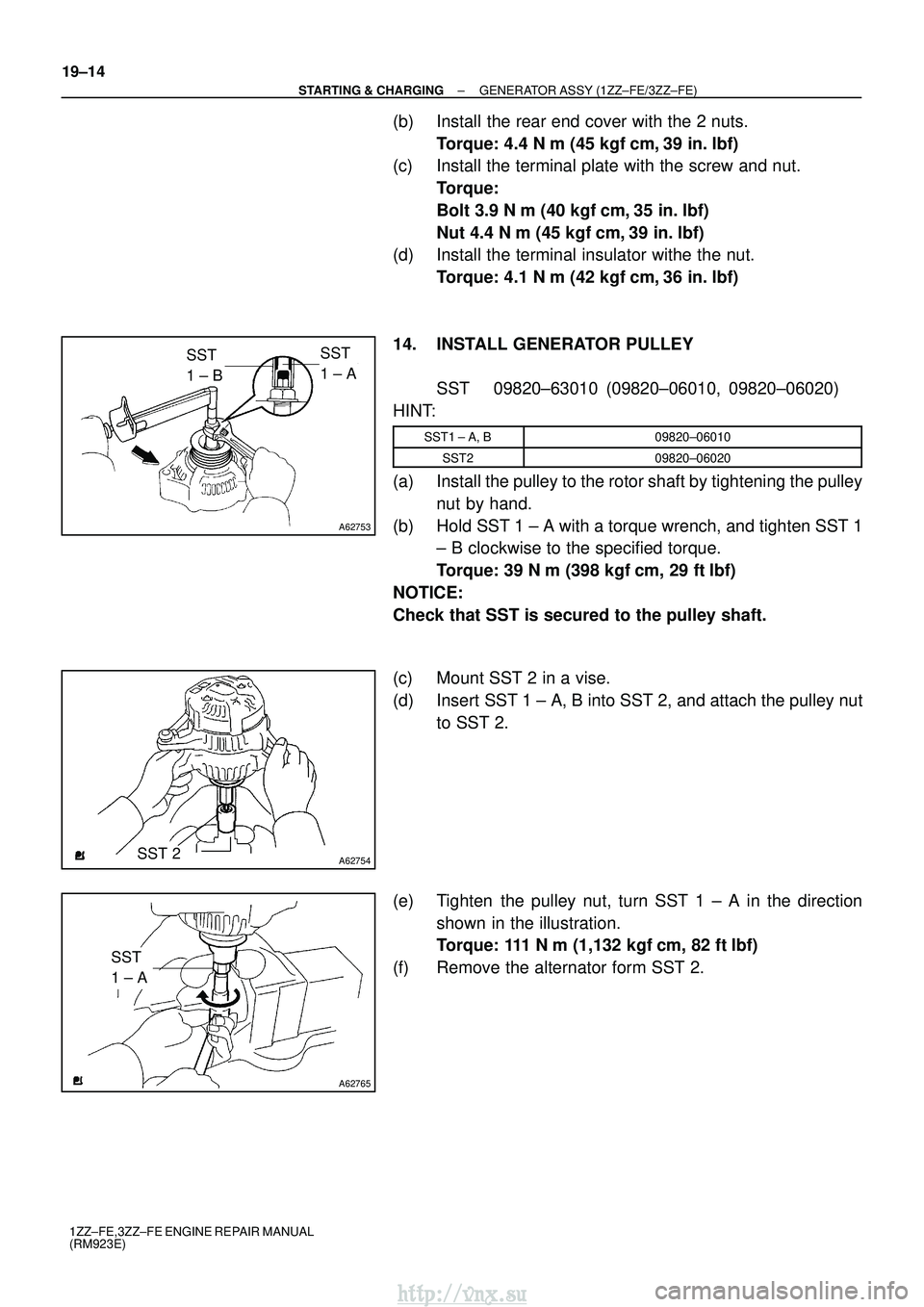
14. INSTALL GENERATOR PULLEY SST 09820±63010 (09820±06010, 09820±06020)
HINT:
SST1 ± A, B09820±06010
SST209820±06020
(a) Install the pulley to the rotor shaft by tightening the pulley nut by hand.
(b) Hold SST 1 ± A with a torque wrench, and tighten SST 1 ± B clockwise to the specified torque.
Torque: 39 N �m (398 kgf� cm, 29 ft�lbf)
NOTICE:
Check that SST is secured to the pulley shaft.
(c) Mount SST 2 in a vise.
(d) Insert SST 1 ± A, B into SST 2, and attach the pulley nut to SST 2.
(e) Tighten the pulley nut, turn SST 1 ± A in the direction shown in the illustration.
Torque: 111 N� m (1,132 kgf�cm, 82 ft �lbf)
(f) Remove the alternator form SST 2.
http://vnx.su
Page 846 of 2234
A62756
SST
1 ± A
SST
1 ± B
±
STARTING & CHARGING GENERATOR ASSY (1ZZ±FE/3ZZ±FE)
19±15
1ZZ±FE,3ZZ±FE ENGINE REPAIR MANUAL
(RM923E)
(g) Turn SST 1 ± B, and remove SST 1 ± A, B.
(h) Turn the pulley, and check that the pulley moves smooth-
ly.
http://vnx.su
Page 849 of 2234
ST0741
A33589
A33590
A37026
A37029
±
STARTING & CHARGING STARTER ASSY (1ZZ±FE/3ZZ±FE)
19±3
1ZZ±FE,3ZZ±FE ENGINE REPAIR MANUAL
(RM923E)
5. REMOVE STARTER CLUTCH SUB±ASSY
(a) Remove drive lever and starter clutch with shock absorb-
er from starter housing.
(b) Using a screwdriver, tap in the stop collar towards the starter clutch.
(c) Using a screwdriver, pry off the snap ring.
(d) Remove the stop collar and starter clutch from the plane- tary shaft.
6. INSPECT STARTER ARMATURE ASSY
(a) Using an ohmmeter, check that there is no continuity be- tween the commutator and armature coil core.
(b) Using an ohmmeter, check that there is continuity be- tween the segments of the commutator.
http://vnx.su
Page 850 of 2234
A37025
A62221
A62222
A62223
19±4
±
STARTING & CHARGING STARTER ASSY (1ZZ±FE/3ZZ±FE)
1ZZ±FE,3ZZ±FE ENGINE REPAIR MANUAL
(RM923E)
(c) Check the commutator for dirty and burn on surface.
If the surface is dirty or burnt, correct it with sandpaper (No. 400)
or a lathe.
(d) Place the commutator on V ± blocks.
(e) Using a dial indicator, measure the circle runout. Maximum circle runout: 0.05 mm (0.0020 in.)
(f) Using a vernier calipers, measure the commutator diame- ter.
Standard diameter: 28 mm (1.102 in.)
Minimum diameter: 27 mm (1.063 in.)
(g) Check that the undercut depth is clean and free of foreign materials. Smooth out the edge.
Standard undercut depth: 0.6 mm (0.024 in.)
Minimum undercut depth: 0.2 mm (0.008 in.)
7. INSPECT FIELD COIL
(a) Using an ohmmeter, check that there is continuity be- tween the lead wire and field coil brush lead.
http://vnx.su
Page 851 of 2234
A62224
A37017
A37020
A62225
Free
Lock
A33580
±
STARTING & CHARGING STARTER ASSY (1ZZ±FE/3ZZ±FE)
19±5
1ZZ±FE,3ZZ±FE ENGINE REPAIR MANUAL
(RM923E)
(b) Using an ohmmeter, check that there is no continuity be-
tween the field coil end and field frame.
8. INSPECT BRUSH
(a) Using a vernier calipers, measure the brush length. Standard length: 14 mm (0.551 in.)
Minimum length: 9 mm (0.354 in.)
9. INSPECT STARTER BRUSH HOLDER ASSY
(a) Using an ohmmeter, check that there is no continuity be- tween the positive (+) and negative (±) brush holders.
10. INSPECT STARTER CLUTCH SUB±ASSY
(a) Rotate the clutch pinion gear clockwise and check that it turns freely. Try to rotate the clutch pinion gear counter-
clockwise and check that it locks.
11. INSPECT MAGNET STARTER SWITCH ASSY
(a) Push in the plunger and check that it returns quickly to its original position.
http://vnx.su