Page 765 of 2234
A01075
A01071
A62782
A62783
±
ENGINE MECHANICAL CYLINDER HEAD ASSY (1ZZ±FE/3ZZ±FE)
14±29
1ZZ±FE,3ZZ±FE ENGINE REPAIR MANUAL
(RM923E)
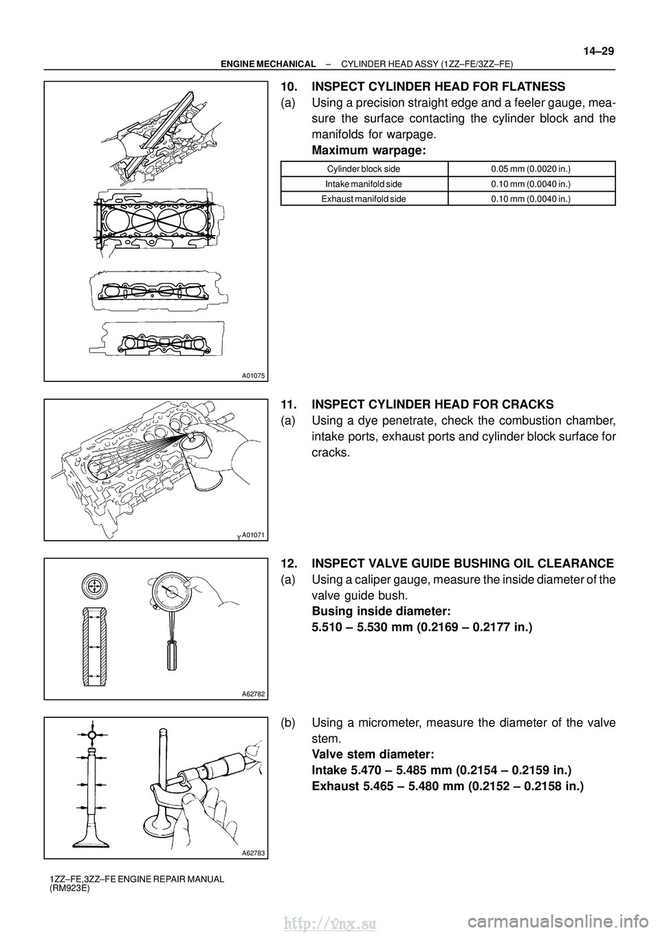
10. INSPECT CYLINDER HEAD FOR FLATNESS
(a) Using a precision straight edge and a feeler gauge, mea-
sure the surface contacting the cylinder block and the
manifolds for warpage.
Maximum warpage:
Cylinder block side0.05 mm (0.0020 in.)
Intake manifold side0.10 mm (0.0040 in.)
Exhaust manifold side0.10 mm (0.0040 in.)
11. INSPECT CYLINDER HEAD FOR CRACKS
(a) Using a dye penetrate, check the combustion chamber,
intake ports, exhaust ports and cylinder block surface for
cracks.
12. INSPECT VALVE GUIDE BUSHING OIL CLEARANCE
(a) Using a caliper gauge, measure the inside diameter of the valve guide bush.
Busing inside diameter:
5.510 ± 5.530 mm (0.2169 ± 0.2177 in.)
(b) Using a micrometer, measure the diameter of the valve stem.
Valve stem diameter:
Intake 5.470 ± 5.485 mm (0.2154 ± 0.2159 in.)
Exhaust 5.465 ± 5.480 mm (0.2152 ± 0.2158 in.)
http://vnx.su
Page 767 of 2234
EM2534
A62785
Margin
Thickness
EM2534
A62785
Margin
Thickness
A62786
Width
±
ENGINE MECHANICAL CYLINDER HEAD ASSY (1ZZ±FE/3ZZ±FE)
14±31
1ZZ±FE,3ZZ±FE ENGINE REPAIR MANUAL
(RM923E)
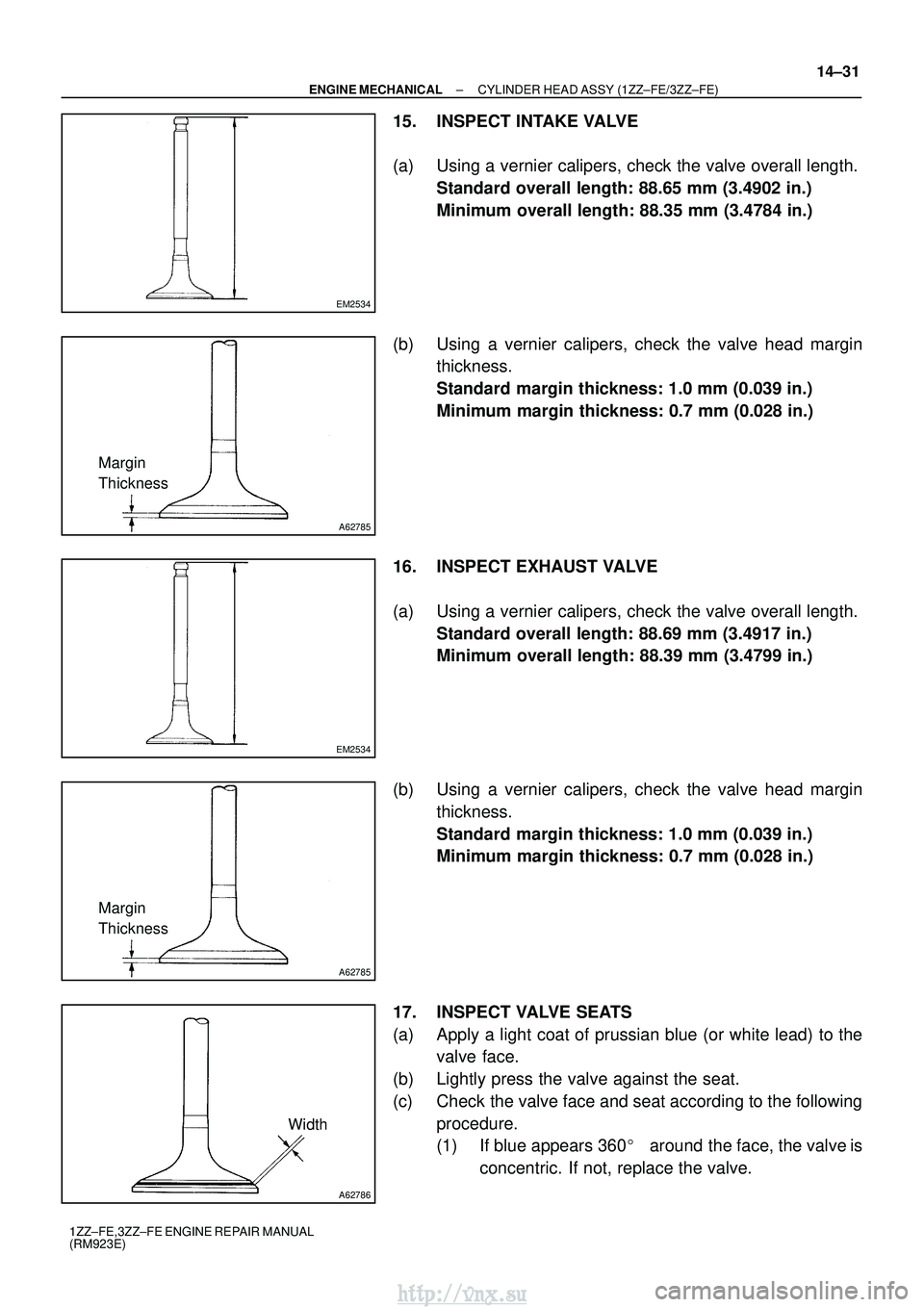
15. INSPECT INTAKE VALVE
(a) Using a vernier calipers, check the valve overall length.
Standard overall length: 88.65 mm (3.4902 in.)
Minimum overall length: 88.35 mm (3.4784 in.)
(b) Using a vernier calipers, check the valve head margin thickness.
Standard margin thickness: 1.0 mm (0.039 in.)
Minimum margin thickness: 0.7 mm (0.028 in.)
16. INSPECT EXHAUST VALVE
(a) Using a vernier calipers, check the valve overall length. Standard overall length: 88.69 mm (3.4917 in.)
Minimum overall length: 88.39 mm (3.4799 in.)
(b) Using a vernier calipers, check the valve head margin thickness.
Standard margin thickness: 1.0 mm (0.039 in.)
Minimum margin thickness: 0.7 mm (0.028 in.)
17. INSPECT VALVE SEATS
(a) Apply a light coat of prussian blue (or white lead) to the valve face.
(b) Lightly press the valve against the seat.
(c) Check the valve face and seat according to the following procedure.
(1) If blue appears 360 �around the face, the valve is
concentric. If not, replace the valve.
http://vnx.su
Page 768 of 2234
A62787
1.0 ± 1.4 mm30
�
45
�
A62788
1.0 ± 1.4 mm 60
�
45 �
P16860
A01080
14±32
±
ENGINE MECHANICAL CYLINDER HEAD ASSY (1ZZ±FE/3ZZ±FE)
1ZZ±FE,3ZZ±FE ENGINE REPAIR MANUAL
(RM923E)
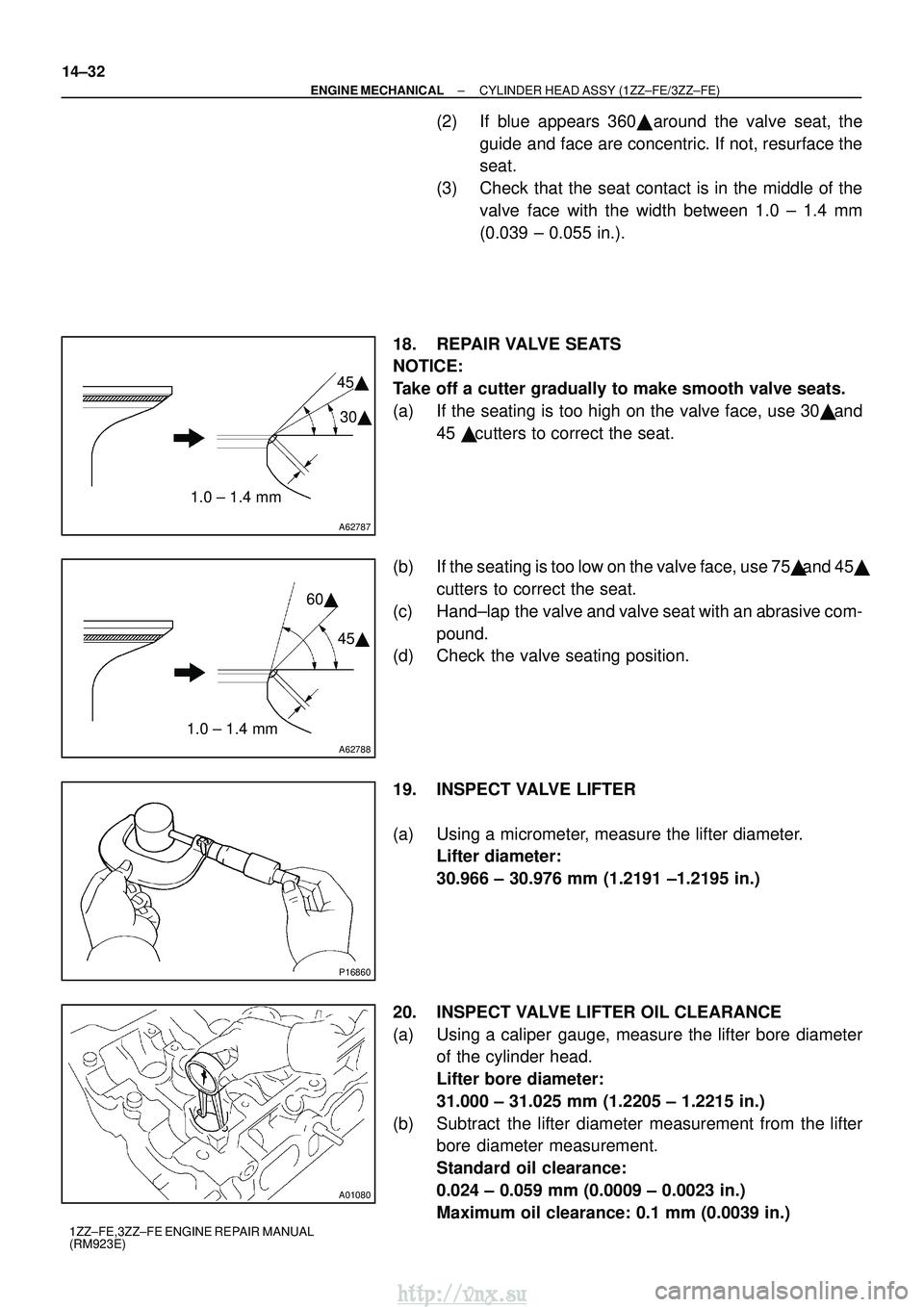
(2) If blue appears 360� around the valve seat, the
guide and face are concentric. If not, resurface the
seat.
(3) Check that the seat contact is in the middle of the valve face with the width between 1.0 ± 1.4 mm
(0.039 ± 0.055 in.).
18. REPAIR VALVE SEATS
NOTICE:
Take off a cutter gradually to make smooth valve seats.
(a) If the seating is too high on the valve face, use 30 � and
45 � cutters to correct the seat.
(b) If the seating is too low on the valve face, use 75 � and 45�
cutters to correct the seat.
(c) Hand±lap the valve and valve seat with an abrasive com- pound.
(d) Check the valve seating position.
19. INSPECT VALVE LIFTER
(a) Using a micrometer, measure the lifter diameter. Lifter diameter:
30.966 ± 30.976 mm (1.2191 ±1.2195 in.)
20. INSPECT VALVE LIFTER OIL CLEARANCE
(a) Using a caliper gauge, measure the lifter bore diameter of the cylinder head.
Lifter bore diameter:
31.000 ± 31.025 mm (1.2205 ± 1.2215 in.)
(b) Subtract the lifter diameter measurement from the lifter bore diameter measurement.
Standard oil clearance:
0.024 ± 0.059 mm (0.0009 ± 0.0023 in.)
Maximum oil clearance: 0.1 mm (0.0039 in.)
http://vnx.su
Page 777 of 2234
140KL±01
A62179
A62185
MarkMark
Mark Timing Chain
Cover Surface
Groove
14±4
±
ENGINE MECHANICAL PARTIAL ENGINE ASSY (1ZZ±FE/3ZZ±FE)
1ZZ±FE,3ZZ±FE ENGINE REPAIR MANUAL
(RM923E)
OVERHAUL
1. REMOVE OIL FILLER CAP SUB±ASSY
(a) Remove the oil filler cap from the cylinder head cover.
2. REMOVE OIL FILLER CAP GASKET
(a) Remove the gasket from the oil filler cap.
3. REMOVE VENTILATION VALVE SUB±ASSY
(a) Remove the ventilation valve from the cylinder head cover.
4. REMOVE SPARK PLUG
(a) Using a spark plug wrench, remove the 4 spark plugs.
5. REMOVE CYLINDER HEAD COVER SUB±ASSY
(a) Remove the 9 bolts, 2 seal washer, 2 nuts and cylinder head cover.
6. REMOVE CYLINDER HEAD COVER GASKET
(a) Remove the gasket from the cylinder head cover. 7. REMOVE WATER PUMP ASSY
(a) Remove the 6 bolts, water pump and O±ring.
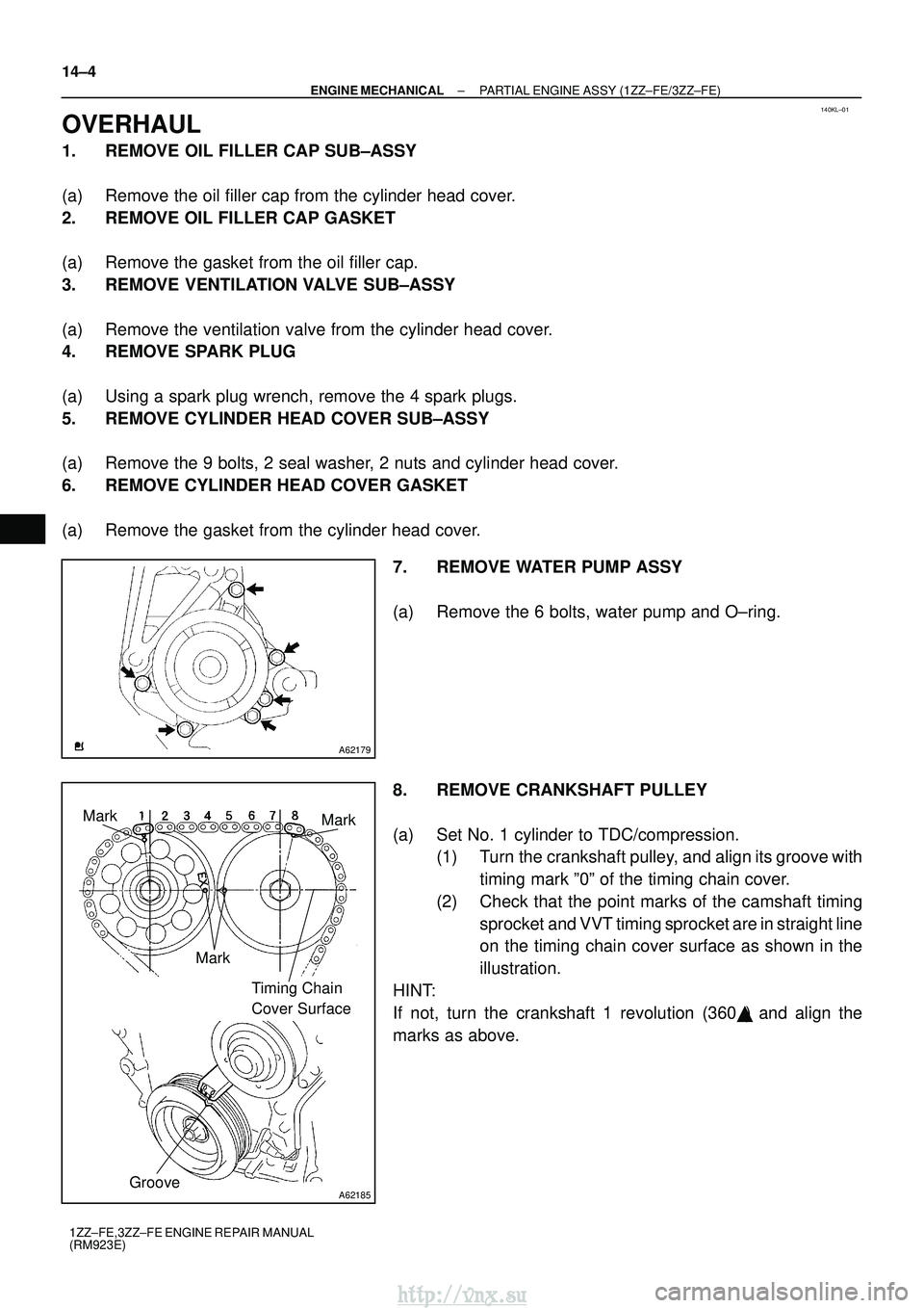
8. REMOVE CRANKSHAFT PULLEY
(a) Set No. 1 cylinder to TDC/compression.(1) Turn the crankshaft pulley, and align its groove with
timing mark º0º of the timing chain cover.
(2) Check that the point marks of the camshaft timing sprocket and VVT timing sprocket are in straight line
on the timing chain cover surface as shown in the
illustration.
HINT:
If not, turn the crankshaft 1 revolution (360 �) and align the
marks as above.
http://vnx.su
Page 779 of 2234
A30857
A62814
4
2531
A32167
A62190
Advance
Side Path
Retard Side
Path
Open
Close
Rubber
Vinyl Tape
Open Close
14±6
±
ENGINE MECHANICAL PARTIAL ENGINE ASSY (1ZZ±FE/3ZZ±FE)
1ZZ±FE,3ZZ±FE ENGINE REPAIR MANUAL
(RM923E)
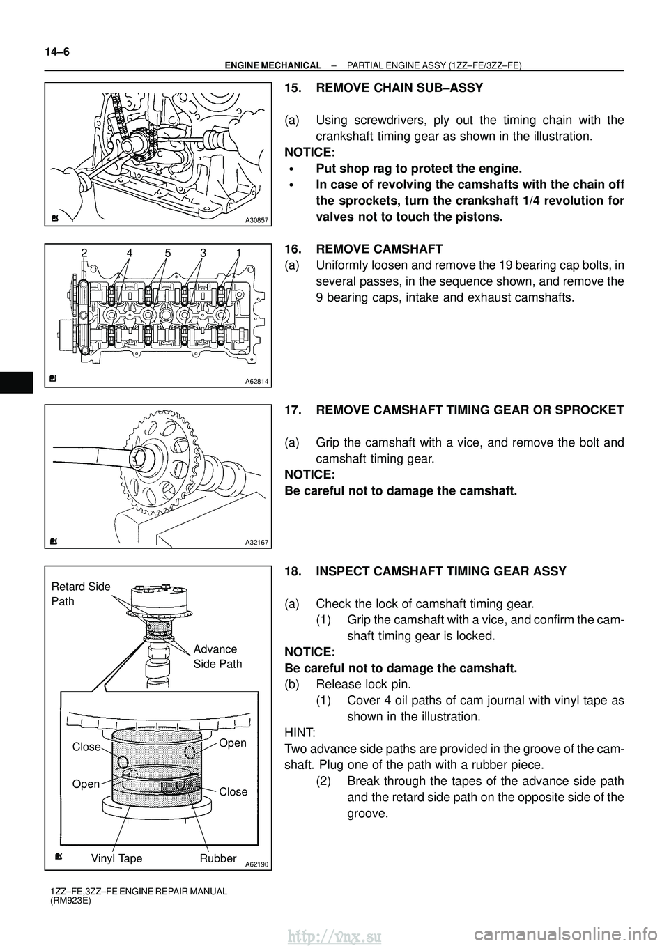
15. REMOVE CHAIN SUB±ASSY
(a) Using screwdrivers, ply out the timing chain with the crankshaft timing gear as shown in the illustration.
NOTICE:
�Put shop rag to protect the engine.
�In case of revolving the camshafts with the chain off
the sprockets, turn the crankshaft 1/4 revolution for
valves not to touch the pistons.
16. REMOVE CAMSHAFT
(a) Uniformly loosen and remove the 19 bearing cap bolts, in several passes, in the sequence shown, and remove the
9 bearing caps, intake and exhaust camshafts.
17. REMOVE CAMSHAFT TIMING GEAR OR SPROCKET
(a) Grip the camshaft with a vice, and remove the bolt and camshaft timing gear.
NOTICE:
Be careful not to damage the camshaft.
18. INSPECT CAMSHAFT TIMING GEAR ASSY
(a) Check the lock of camshaft timing gear. (1) Grip the camshaft with a vice, and confirm the cam-
shaft timing gear is locked.
NOTICE:
Be careful not to damage the camshaft.
(b) Release lock pin. (1) Cover 4 oil paths of cam journal with vinyl tape asshown in the illustration.
HINT:
Two advance side paths are provided in the groove of the cam-
shaft. Plug one of the path with a rubber piece. (2) Break through the tapes of the advance side pathand the retard side path on the opposite side of the
groove.
http://vnx.su
Page 780 of 2234
A62191
Advanced
Side Path
Retard
Side Path
A62192
Hold Pressure
Decompress Advanced
Side Path
Retard
Side Path
±
ENGINE MECHANICAL PARTIAL ENGINE ASSY (1ZZ±FE/3ZZ±FE)
14±7
1ZZ±FE,3ZZ±FE ENGINE REPAIR MANUAL
(RM923E)
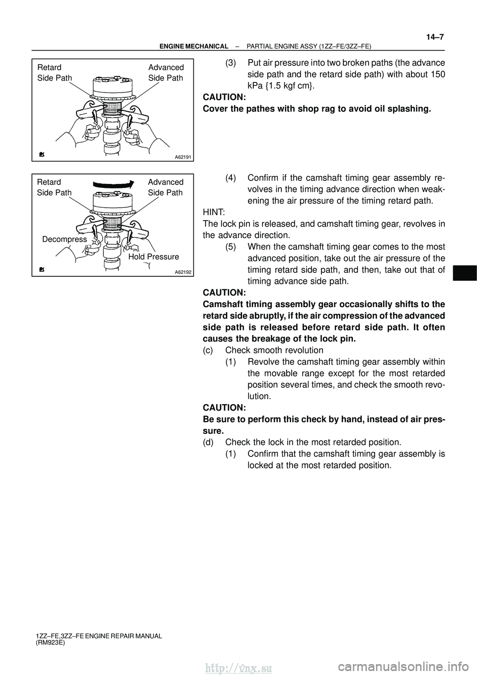
(3) Put air pressure into two broken paths (the advance
side path and the retard side path) with about 150
kPa {1.5 kgf� cm}.
CAUTION:
Cover the pathes with shop rag to avoid oil splashing.
(4) Confirm if the camshaft timing gear assembly re-volves in the timing advance direction when weak-
ening the air pressure of the timing retard path.
HINT:
The lock pin is released, and camshaft timing gear, revolves in
the advance direction. (5) When the camshaft timing gear comes to the mostadvanced position, take out the air pressure of the
timing retard side path, and then, take out that of
timing advance side path.
CAUTION:
Camshaft timing assembly gear occasionally shifts to the
retard side abruptly, if the air compression of the advanced
side path is released before retard side path. It often
causes the breakage of the lock pin.
(c) Check smooth revolution (1) Revolve the camshaft timing gear assembly withinthe movable range except for the most retarded
position several times, and check the smooth revo-
lution.
CAUTION:
Be sure to perform this check by hand, instead of air pres-
sure.
(d) Check the lock in the most retarded position. (1) Confirm that the camshaft timing gear assembly islocked at the most retarded position.
http://vnx.su
Page 783 of 2234
A62817SST
A62202
Cut Position
A01153
A01456
14±10
±
ENGINE MECHANICAL PARTIAL ENGINE ASSY (1ZZ±FE/3ZZ±FE)
1ZZ±FE,3ZZ±FE ENGINE REPAIR MANUAL
(RM923E)
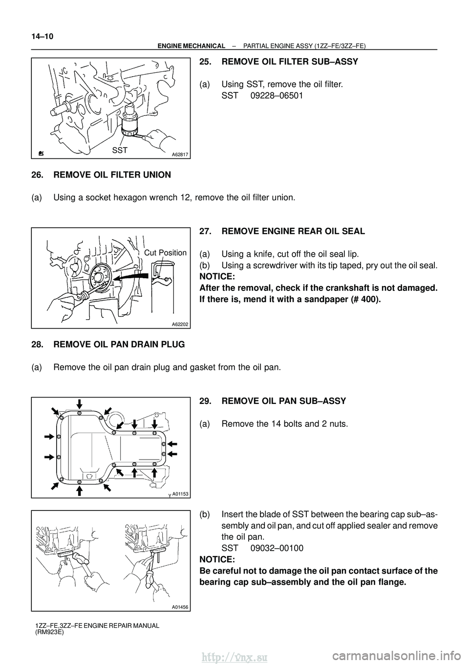
25. REMOVE OIL FILTER SUB±ASSY
(a) Using SST, remove the oil filter. SST 09228±06501
26. REMOVE OIL FILTER UNION
(a) Using a socket hexagon wrench 12, remove the oil filter union. 27. REMOVE ENGINE REAR OIL SEAL
(a) Using a knife, cut off the oil seal lip.
(b) Using a screwdriver with its tip taped, pry out the oil seal.
NOTICE:
After the removal, check if the crankshaft is not damaged.
If there is, mend it with a sandpaper (# 400).
28. REMOVE OIL PAN DRAIN PLUG
(a) Remove the oil pan drain plug and gasket from the oil pan. 29. REMOVE OIL PAN SUB±ASSY
(a) Remove the 14 bolts and 2 nuts.
(b) Insert the blade of SST between the bearing cap sub±as-sembly and oil pan, and cut off applied sealer and remove
the oil pan.
SST 09032±00100
NOTICE:
Be careful not to damage the oil pan contact surface of the
bearing cap sub±assembly and the oil pan flange.
http://vnx.su
Page 784 of 2234
A62818
Raise
Move
Lock
A62819
Measuring Area
012345 16
A30206
±
ENGINE MECHANICAL PARTIAL ENGINE ASSY (1ZZ±FE/3ZZ±FE)
14±11
1ZZ±FE,3ZZ±FE ENGINE REPAIR MANUAL
(RM923E)
30. REMOVE OIL STRAINER SUB±ASSY
(a) Remove the bolt, 2 nuts, oil strainer and gasket.
31. REMOVE CYLINDER BLOCK WATER DRAIN COCK SUB±ASSY
(a) Remove the cylinder block water drain cock from the cylinder block.
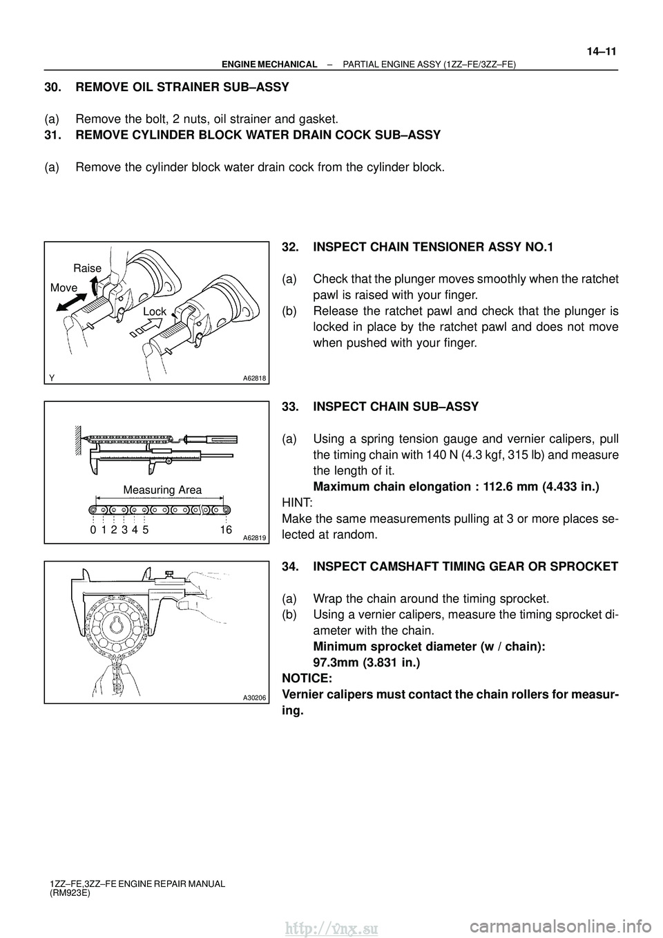
32. INSPECT CHAIN TENSIONER ASSY NO.1
(a) Check that the plunger moves smoothly when the ratchetpawl is raised with your finger.
(b) Release the ratchet pawl and check that the plunger is locked in place by the ratchet pawl and does not move
when pushed with your finger.
33. INSPECT CHAIN SUB±ASSY
(a) Using a spring tension gauge and vernier calipers, pull the timing chain with 140 N (4.3 kgf, 315 lb) and measure
the length of it.
Maximum chain elongation : 112.6 mm (4.433 in.)
HINT:
Make the same measurements pulling at 3 or more places se-
lected at random.
34. INSPECT CAMSHAFT TIMING GEAR OR SPROCKET
(a) Wrap the chain around the timing sprocket.
(b) Using a vernier calipers, measure the timing sprocket di- ameter with the chain.
Minimum sprocket diameter (w / chain):
97.3mm (3.831 in.)
NOTICE:
Vernier calipers must contact the chain rollers for measur-
ing.
http://vnx.su