Page 786 of 2234
EM1628
EM2011
EM2538
±
ENGINE MECHANICAL PARTIAL ENGINE ASSY (1ZZ±FE/3ZZ±FE)
14±13
1ZZ±FE,3ZZ±FE ENGINE REPAIR MANUAL
(RM923E)
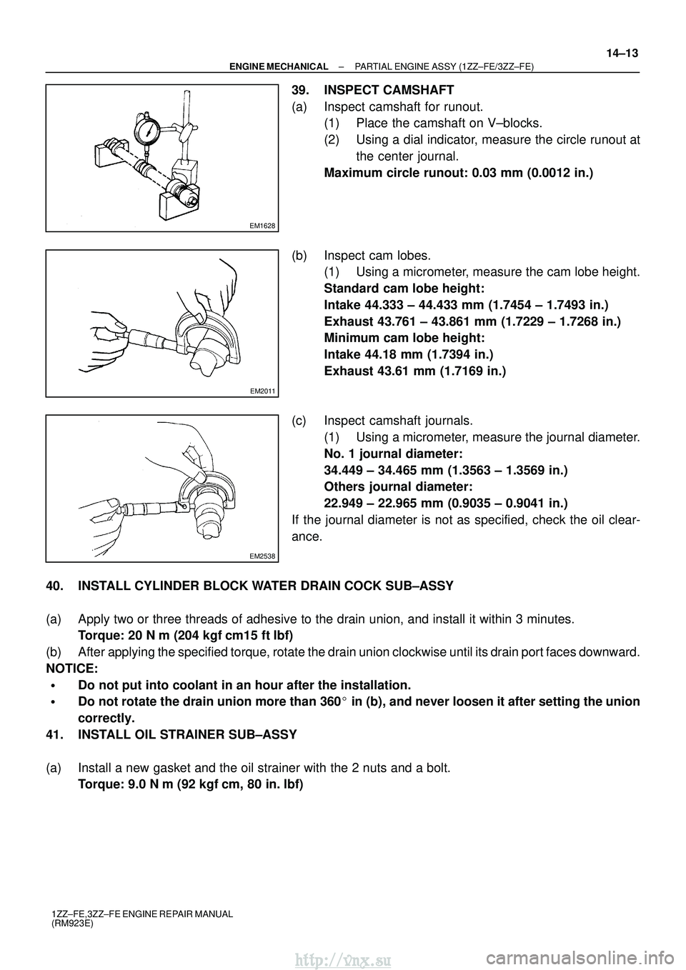
39. INSPECT CAMSHAFT
(a) Inspect camshaft for runout.
(1) Place the camshaft on V±blocks.
(2) Using a dial indicator, measure the circle runout at
the center journal.
Maximum circle runout: 0.03 mm (0.0012 in.)
(b) Inspect cam lobes. (1) Using a micrometer, measure the cam lobe height.
Standard cam lobe height:
Intake 44.333 ± 44.433 mm (1.7454 ± 1.7493 in.)
Exhaust 43.761 ± 43.861 mm (1.7229 ± 1.7268 in.)
Minimum cam lobe height:
Intake 44.18 mm (1.7394 in.)
Exhaust 43.61 mm (1.7169 in.)
(c) Inspect camshaft journals. (1) Using a micrometer, measure the journal diameter.
No. 1 journal diameter:
34.449 ± 34.465 mm (1.3563 ± 1.3569 in.)
Others journal diameter:
22.949 ± 22.965 mm (0.9035 ± 0.9041 in.)
If the journal diameter is not as specified, check the oil clear-
ance.
40. INSTALL CYLINDER BLOCK WATER DRAIN COCK SUB±ASSY
(a) Apply two or three threads of adhesive to the drain union, and install i\
t within 3 minutes. Torque: 20 N �m (204 kgf� cm15 ft�lbf)
(b) After applying the specified torque, rotate the drain union clockwise until i\
ts drain port faces downward.
NOTICE:
�Do not put into coolant in an hour after the installation.
�Do not rotate the drain union more than 360� in (b), and never loosen it after setting the union
correctly.
41. INSTALL OIL STRAINER SUB±ASSY
(a) Install a new gasket and the oil strainer with the 2 nuts and a bolt. Torque: 9.0 N �m (92 kgf �cm, 80 in. �lbf)
http://vnx.su
Page 787 of 2234
A62821
Seal Width 4 ± 5 mm
6 mm Seal Packing
A62822
SST
A62817SST
14±14
±
ENGINE MECHANICAL PARTIAL ENGINE ASSY (1ZZ±FE/3ZZ±FE)
1ZZ±FE,3ZZ±FE ENGINE REPAIR MANUAL
(RM923E)
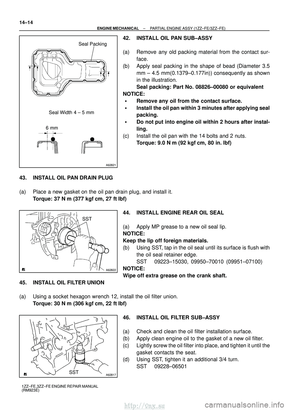
42. INSTALL OIL PAN SUB±ASSY
(a) Remove any old packing material from the contact sur- face.
(b) Apply seal packing in the shape of bead (Diameter 3.5 mm ± 4.5 mm(0.1379±0.177in)) consequently as shown
in the illustration.
Seal packing: Part No. 08826±00080 or equivalent
NOTICE:
�Remove any oil from the contact surface.
�Install the oil pan within 3 minutes after applying seal
packing.
�Do not put into engine oil within 2 hours after instal-
ling.
(c) Install the oil pan with the 14 bolts and 2 nuts. Torque: 9.0 N �m (92 kgf �cm, 80 in. �lbf)
43. INSTALL OIL PAN DRAIN PLUG
(a) Place a new gasket on the oil pan drain plug, and install it. Torque: 37 N �m (377 kgf� cm, 27 ft�lbf)
44. INSTALL ENGINE REAR OIL SEAL
(a) Apply MP grease to a new oil seal lip.
NOTICE:
Keep the lip off foreign materials.
(b) Using SST, tap in the oil seal until its surface is flush with the oil seal retainer edge.
SST 09223±15030, 09950±70010 (09951±07100)
NOTICE:
Wipe off extra grease on the crank shaft.
45. INSTALL OIL FILTER UNION
(a) Using a socket hexagon wrench 12, install the oil filter union. Torque: 30 N �m (306 kgf� cm, 22 ft�lbf)
46. INSTALL OIL FILTER SUB±ASSY
(a) Check and clean the oil filter installation surface.
(b) Apply clean engine oil to the gasket of a new oil filter.
(c) Lightly screw the oil filter into place, and tighten it until the gasket contacts the seat.
(d) Using SST, tighten it an additional 3/4 turn.
SST 09228±06501
http://vnx.su
Page 788 of 2234
A30890
A62826
Lot No.
A62816
84 2 59731610
A62823
Paint Mark
90 �
Front
A62815
Mesh
±
ENGINE MECHANICAL PARTIAL ENGINE ASSY (1ZZ±FE/3ZZ±FE)
14±15
1ZZ±FE,3ZZ±FE ENGINE REPAIR MANUAL
(RM923E)
47. INSTALL OIL PUMP ASSY
(a) Engage the spline teeth of the oil pump drive rotor with the
large teeth of the crankshaft, and side the oil pump.
(b) Install the oil pump with the 5 bolts. Torque: 9.0 N �m (92 kgf �cm, 80 in. �lbf)
48. INSTALL CYLINDER HEAD GASKET
(a) Place a new cylinder head gasket on the cylinder block surface with the Lot No. stamp upward.
NOTICE:
�Pay attention to the installation direction.
�Place the cylinder head quietly in order not to damage
the gasket with the bottom part of the head.
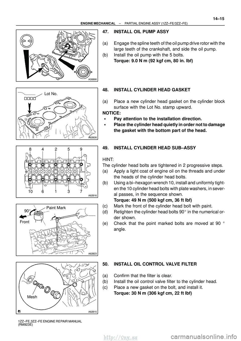
49. INSTALL CYLINDER HEAD SUB±ASSY
HINT:
The cylinder head bolts are tightened in 2 progressive steps.
(a) Apply a light coat of engine oil on the threads and under the heads of the cylinder head bolts.
(b) Using a bi±hexagon wrench 10, install and uniformly tight- en the 10 cylinder head bolts with plate washers, in sever-
al passes, in the sequence shown.
Torque: 49 N �m (500 kgf� cm, 36 ft�lbf)
(c) Mark the front of the cylinder head bolt with paint.
(d) Retighten the cylinder head bolts 90 � in the numerical or-
der shown.
(e) Check that the point marked bolts are moved at 90 �
angle.
50. INSTALL OIL CONTROL VALVE FILTER
(a) Confirm that the filter is clear.
(b) Install the oil control valve filter to the cylinder head.
(c) Place a new gasket on the bolt, and install it. Torque: 30 N �m (306 kgf� cm, 22 ft�lbf)
http://vnx.su
Page 789 of 2234
A62824
Straight Pin
Key Groove
A32167
A62150
14±16
±
ENGINE MECHANICAL PARTIAL ENGINE ASSY (1ZZ±FE/3ZZ±FE)
1ZZ±FE,3ZZ±FE ENGINE REPAIR MANUAL
(RM923E)
51. INSTALL CAMSHAFT TIMING OIL CONTROL VALVE ASSY
(a) Install a new O±ring to the camshaft timing oil control valve.
(b) Install the camshaft timing oil control valve with the bolt. Torque: 9.0 N �m (92 kgf �cm, 80 in. �lbf)
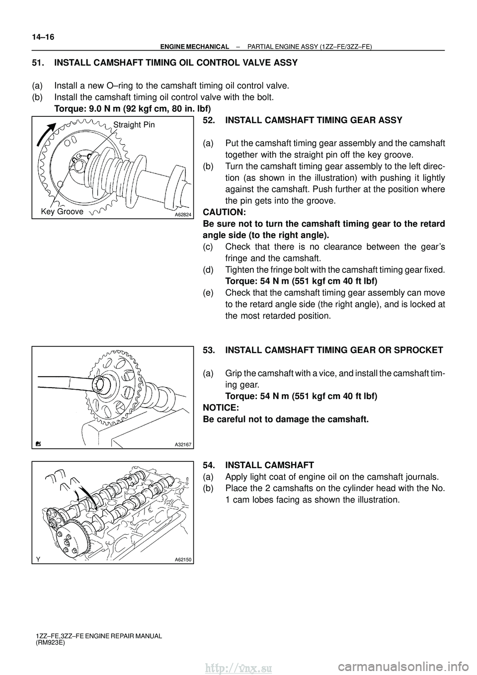
52. INSTALL CAMSHAFT TIMING GEAR ASSY
(a) Put the camshaft timing gear assembly and the camshaft together with the straight pin off the key groove.
(b) Turn the camshaft timing gear assembly to the left direc- tion (as shown in the illustration) with pushing it lightly
against the camshaft. Push further at the position where
the pin gets into the groove.
CAUTION:
Be sure not to turn the camshaft timing gear to the retard
angle side (to the right angle).
(c) Check that there is no clearance between the gear's fringe and the camshaft.
(d) Tighten the fringe bolt with the camshaft timing gear fixed. Torque: 54 N� m (551 kgf�cm 40 ft�lbf)
(e) Check that the camshaft timing gear assembly can move to the retard angle side (the right angle), and is locked at
the most retarded position.
53. INSTALL CAMSHAFT TIMING GEAR OR SPROCKET
(a) Grip the camshaft with a vice, and install the camshaft tim- ing gear.
Torque: 54 N �m (551 kgf� cm 40 ft�lbf)
NOTICE:
Be careful not to damage the camshaft.
54. INSTALL CAMSHAFT
(a) Apply light coat of engine oil on the camshaft journals.
(b) Place the 2 camshafts on the cylinder head with the No. 1 cam lobes facing as shown the illustration.
http://vnx.su
Page 792 of 2234
A62176
Chain Cover
Groove
Cylinder Head
Groove Seal Width
4 ± 5 mm
A B
7 mm 4.5 mm 3 mm
6 mm
12 mm
B
A
A ± A B ± B A
A
A62177
Raise
Push
Hook
Pin
A62178
Push
±
ENGINE MECHANICAL PARTIAL ENGINE ASSY (1ZZ±FE/3ZZ±FE)
14±19
1ZZ±FE,3ZZ±FE ENGINE REPAIR MANUAL
(RM923E)
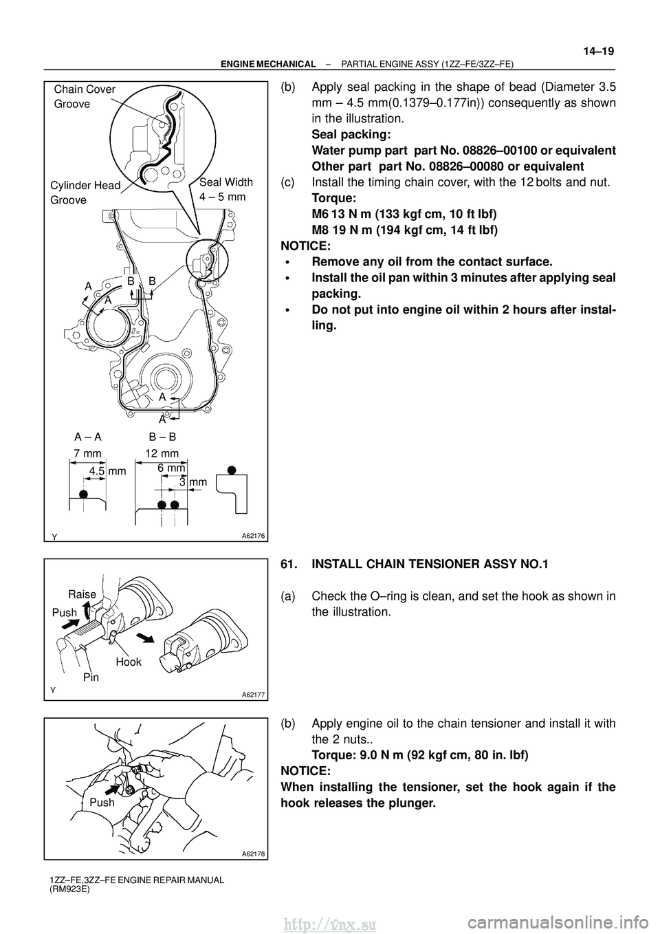
(b) Apply seal packing in the shape of bead (Diameter 3.5
mm ± 4.5 mm(0.1379±0.177in)) consequently as shown
in the illustration.
Seal packing:
Water pump part part No. 08826±00100 or equivalent
Other part part No. 08826±00080 or equivalent
(c) Install the timing chain cover, with the 12 bolts and nut.
Torque:
M6 13 N �m (133 kgf� cm, 10 ft�lbf)
M8 19 N �m (194 kgf� cm, 14 ft�lbf)
NOTICE:
�Remove any oil from the contact surface.
�Install the oil pan within 3 minutes after applying seal
packing.
�Do not put into engine oil within 2 hours after instal-
ling.
61. INSTALL CHAIN TENSIONER ASSY NO.1
(a) Check the O±ring is clean, and set the hook as shown in the illustration.
(b) Apply engine oil to the chain tensioner and install it with the 2 nuts..
Torque: 9.0 N �m (92 kgf �cm, 80 in. �lbf)
NOTICE:
When installing the tensioner, set the hook again if the
hook releases the plunger.
http://vnx.su
Page 793 of 2234
A62837SST
A62180
DisconnectHook
Pin Turn
A62181
Plunger
Turn
Push
A10085
A62179
A
ABB
B
B
14±20
±
ENGINE MECHANICAL PARTIAL ENGINE ASSY (1ZZ±FE/3ZZ±FE)
1ZZ±FE,3ZZ±FE ENGINE REPAIR MANUAL
(RM923E)
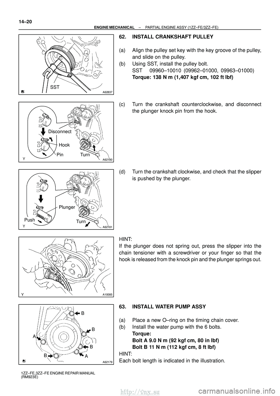
62. INSTALL CRANKSHAFT PULLEY
(a) Align the pulley set key with the key groove of the pulley, and slide on the pulley.
(b) Using SST, install the pulley bolt. SST 09960±10010 (09962±01000, 09963±01000)
Torque: 138 N� m (1,407 kgf�cm, 102 ft� lbf)
(c) Turn the crankshaft counterclockwise, and disconnect the plunger knock pin from the hook.
(d) Turn the crankshaft clockwise, and check that the slipper is pushed by the plunger.
HINT:
If the plunger does not spring out, press the slipper into the
chain tensioner with a screwdriver or your finger so that the
hook is released from the knock pin and the plunger springs out.
63. INSTALL WATER PUMP ASSY
(a) Place a new O±ring on the timing chain cover.
(b) Install the water pump with the 6 bolts. Torque:
Bolt A 9.0 N� m (92 kgf�cm, 80 in� lbf)
Bolt B 11 N� m (112 kgf�cm, 8 ft� lbf)
HINT:
Each bolt length is indicated in the illustration.
http://vnx.su
Page 794 of 2234
A62185
MarkMark
Mark Timing Chain
Cover Surface
Groove
A01131
A01132
±
ENGINE MECHANICAL PARTIAL ENGINE ASSY (1ZZ±FE/3ZZ±FE)
14±21
1ZZ±FE,3ZZ±FE ENGINE REPAIR MANUAL
(RM923E)
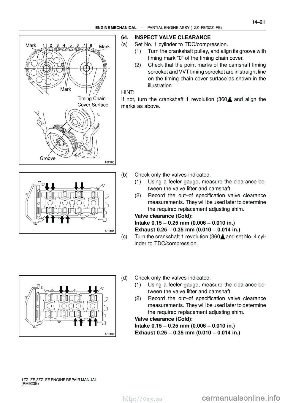
64. INSPECT VALVE CLEARANCE
(a) Set No. 1 cylinder to TDC/compression.
(1) Turn the crankshaft pulley, and align its groove with
timing mark º0º of the timing chain cover.
(2) Check that the point marks of the camshaft timing sprocket and VVT timing sprocket are in straight line
on the timing chain cover surface as shown in the
illustration.
HINT:
If not, turn the crankshaft 1 revolution (360 �) and align the
marks as above.
(b) Check only the valves indicated. (1) Using a feeler gauge, measure the clearance be-tween the valve lifter and camshaft.
(2) Record the out±of specification valve clearance measurements. They will be used later to determine
the required replacement adjusting shim.
Valve clearance (Cold):
Intake 0.15 ± 0.25 mm (0.006 ± 0.010 in.)
Exhaust 0.25 ± 0.35 mm (0.010 ± 0.014 in.)
(c) Turn the crankshaft 1 revolution (360 �) and set No. 4 cyl-
inder to TDC/compression.
(d) Check only the valves indicated. (1) Using a feeler gauge, measure the clearance be-tween the valve lifter and camshaft.
(2) Record the out±of specification valve clearance measurements. They will be used later to determine
the required replacement adjusting shim.
Valve clearance (Cold):
Intake 0.15 ± 0.25 mm (0.006 ± 0.010 in.)
Exhaust 0.25 ± 0.35 mm (0.010 ± 0.014 in.)
http://vnx.su
Page 798 of 2234
A62185
MarkMark
Mark Timing Chain
Cover Surface
Groove
A62177
Raise
Push
Hook
Pin
A62178
Push
A62180
Disconnect
Hook
Pin Turn
±
ENGINE MECHANICAL PARTIAL ENGINE ASSY (1ZZ±FE/3ZZ±FE)
14±25
1ZZ±FE,3ZZ±FE ENGINE REPAIR MANUAL
(RM923E)
(t) Check the match marks on the timing chain and camshaft
timing sprockets, and then the alignment of the pulley
groove with timing mark of the chain cover as shown in the
illustration.
(u) Install chain tensioner. (1) Check the O±ring is clean, and set the hook asshown in the illustration.
(2) Apply engine oil to the chain tensioner and install it.
Torque: 9.0 N� m (92 kgf�cm, 80 in� lbf)
NOTICE:
When installing the tensioner, set the hook again if the
hook release the plunger.
(3) Turn the crankshaft counterclockwise, and discon-nect the plunger knock pin from the hook.
http://vnx.su