Page 404 of 2234

A09656
A79144
A80110
±
FUELINJECTOR ASSY(1CD±FTV)
11±61
AVENSIS REPAIR MANUAL (RM1018E)
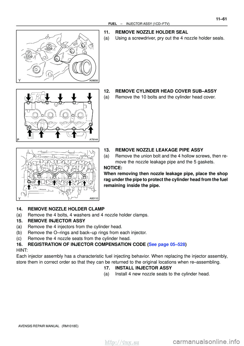
11.REMOVE NOZZLE HOLDER SEAL
(a)Using a screwdriver, pry out the 4 nozzle holder seals.
12.REMOVE CYLINDER HEAD COVER SUB±ASSY
(a)Remove the 10 bolts and the cylinder head cover.
13.REMOVE NOZZLE LEAKAGE PIPE ASSY
(a)Remove the union bolt and the 4 hollow screws, then re-
move the nozzle leakage pipe and the 5 gaskets.
NOTICE:
When removing then nozzle leakage pipe, place the shop
rag under the pipe to protect the cylinder head from the fuel
remaining inside the pipe.
14.REMOVE NOZZLE HOLDER CLAMP
(a)Remove the 4 bolts, 4 washers and 4 nozzle holder clamps.
15.REMOVE INJECTOR ASSY
(a)Remove the 4 injectors from the cylinder head.
(b)Remove the O±rings and back±up rings from each injector.
(c)Remove the 4 nozzle seats from the cylinder head.
16.REGISTRATION OF INJECTOR COMPENSATION CODE (See page 05±528)
HINT:
Each injector assembly has a characteristic fuel injecting behavior. When replacing the injector assembly,
store them in correct order so that they can be returned to the original\
locations when re±assembling. 17. INSTALL INJECTOR ASSY
(a) Install 4 new nozzle seats to the cylinder head.
http://vnx.su
Page 761 of 2234

A01191
A01038
Seal Packing
A62801
793
481062
15
A62806
Paint Mark
Front 90
�
14±52
±
ENGINE MECHANICAL CYLINDER BLOCK (1ZZ±FE/3ZZ±FE)
1ZZ±FE,3ZZ±FE ENGINE REPAIR MANUAL
(RM923E)
(c) Install the 2 thrust washers under the No. 3 journal posi- tion of the cylinder block with the oil grooves facing out-
ward.
(d) Apply engine oil to upper bearing and install the crank- shaft on the cylinder block.
(e) Apply a light coat of engine oil on the bolt threads, the bolt seats, and the bearings of the bearing cap sub±assy.
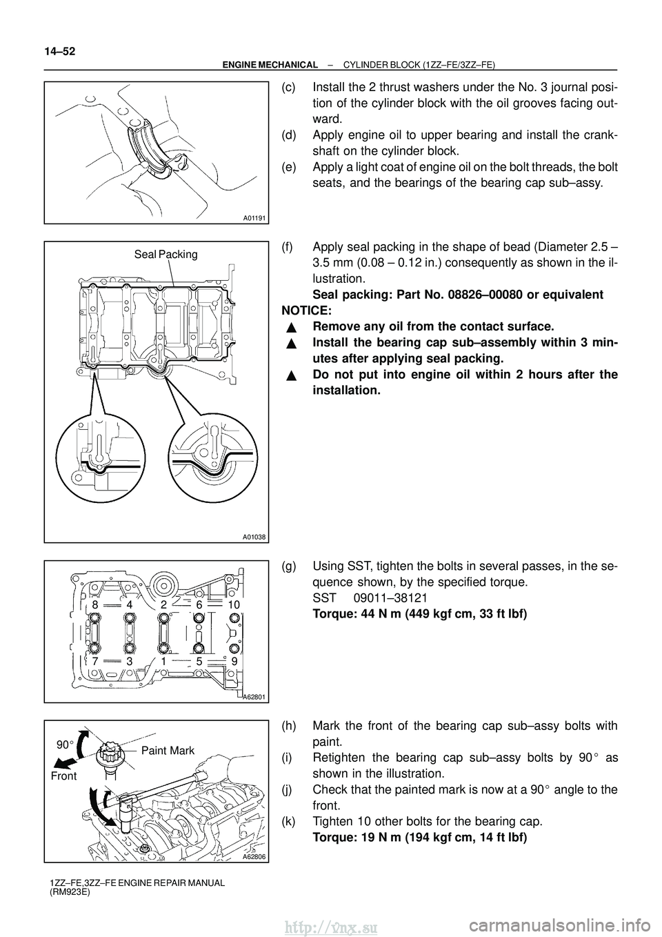
(f) Apply seal packing in the shape of bead (Diameter 2.5 ± 3.5 mm (0.08 ± 0.12 in.) consequently as shown in the il-
lustration.
Seal packing: Part No. 08826±00080 or equivalent
NOTICE:
�Remove any oil from the contact surface.
�Install the bearing cap sub±assembly within 3 min-
utes after applying seal packing.
�Do not put into engine oil within 2 hours after the
installation.
(g) Using SST, tighten the bolts in several passes, in the se- quence shown, by the specified torque.
SST 09011±38121
Torque: 44 N �m (449 kgf� cm, 33 ft�lbf)
(h) Mark the front of the bearing cap sub±assy bolts with paint.
(i) Retighten the bearing cap sub±assy bolts by 90 � as
shown in the illustration.
(j) Check that the painted mark is now at a 90 � angle to the
front.
(k) Tighten 10 other bolts for the bearing cap.
Torque: 19 N �m (194 kgf� cm, 14 ft�lbf)
http://vnx.su
Page 764 of 2234

140KN±01
A62780
SST
A62781
SST
14±28
±
ENGINE MECHANICAL CYLINDER HEAD ASSY (1ZZ±FE/3ZZ±FE)
1ZZ±FE,3ZZ±FE ENGINE REPAIR MANUAL
(RM923E)
OVERHAUL
1. REMOVE W/HEAD TAPER SCREW PLUG NO.2
(a) Using a socket hexagon wench 10, remove the taper screw plug and gasket.\
2. REMOVE VALVE LIFTER
(a) Remove the 16 valve lifters from the cylinder head. 3. REMOVE INNER COMPRESSION SPRING
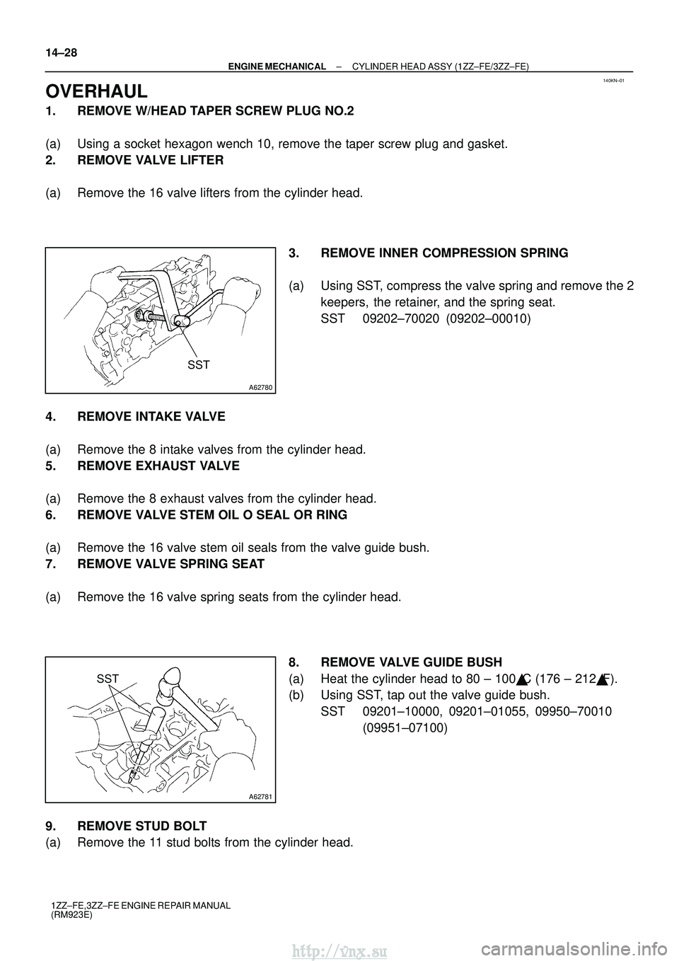
(a) Using SST, compress the valve spring and remove the 2keepers, the retainer, and the spring seat.
SST 09202±70020 (09202±00010)
4. REMOVE INTAKE VALVE
(a) Remove the 8 intake valves from the cylinder head.
5. REMOVE EXHAUST VALVE
(a) Remove the 8 exhaust valves from the cylinder head.
6. REMOVE VALVE STEM OIL O SEAL OR RING
(a) Remove the 16 valve stem oil seals from the valve guide bush.
7. REMOVE VALVE SPRING SEAT
(a) Remove the 16 valve spring seats from the cylinder head. 8. REMOVE VALVE GUIDE BUSH
(a) Heat the cylinder head to 80 ± 100�C (176 ± 212 �F).
(b) Using SST, tap out the valve guide bush.
SST 09201±10000, 09201±01055, 09950±70010 (09951±07100)
9. REMOVE STUD BOLT
(a) Remove the 11 stud bolts from the cylinder head.
http://vnx.su
Page 1009 of 2234

2600L±02
F44617
Front:AB
F44618
Rear:
C D
SA3213
A
D B
Front
C
F44619
26±6
±
FRONT SUSPENSION FRONT WHEEL ALIGNMENT
AVENSIS REPAIR MANUAL (RM1018E)
FRONT WHEEL ALIGNMENT
ADJUSTMENT
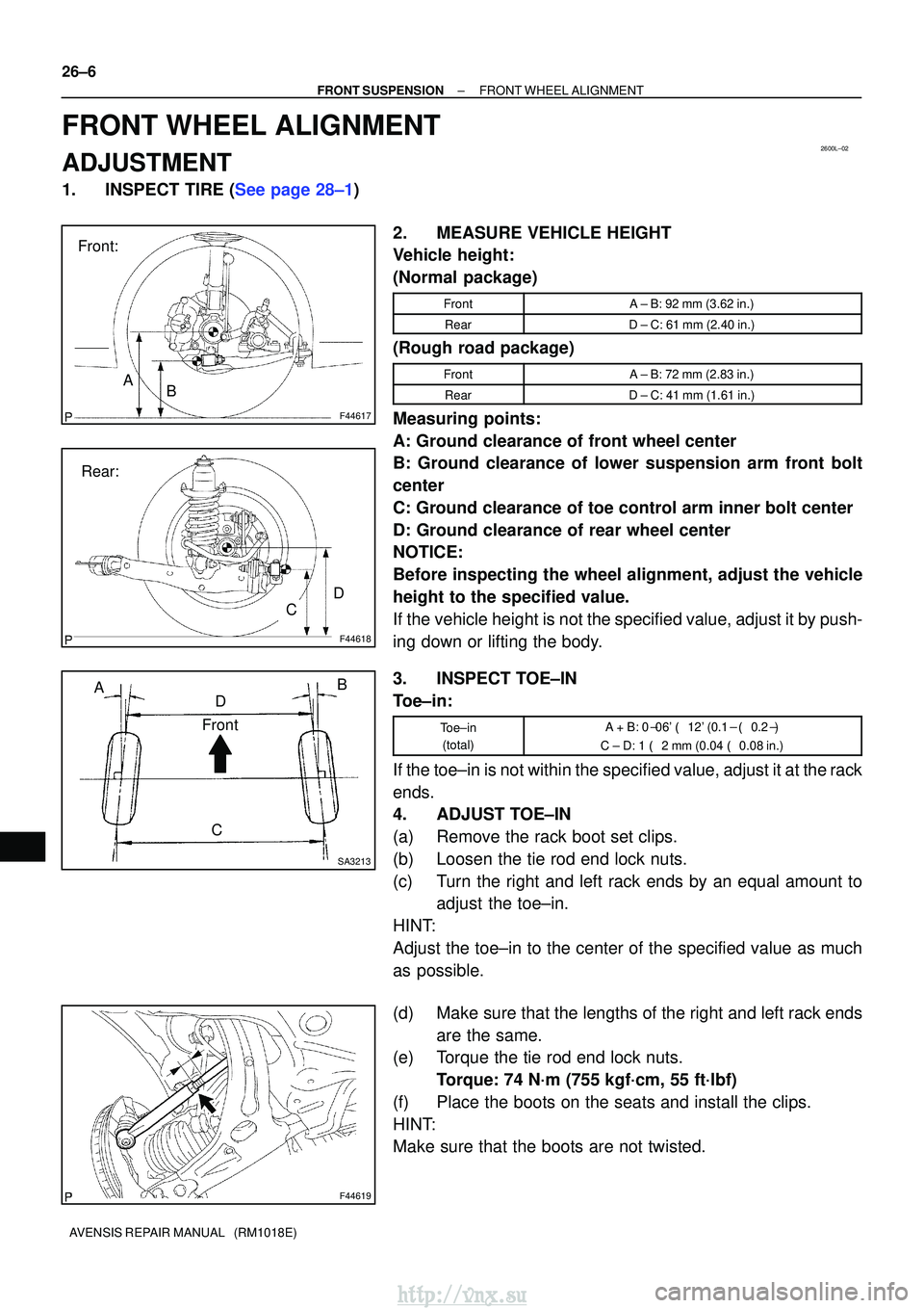
1.INSPECT TIRE (See page 28±1) 2. MEASURE VEHICLE HEIGHT
Vehicle height:
(Normal package)
FrontA ± B: 92 mm (3.62 in.)
RearD ± C: 61 mm (2.40 in.)
(Rough road package)
FrontA ± B: 72 mm (2.83 in.)
RearD ± C: 41 mm (1.61 in.)
Measuring points:
A: Ground clearance of front wheel center
B: Ground clearance of lower suspension arm front bolt
center
C: Ground clearance of toe control arm inner bolt center
D: Ground clearance of rear wheel center
NOTICE:
Before inspecting the wheel alignment, adjust the vehicle
height to the specified value.
If the vehicle height is not the specified value, adjust it by push-
ing down or lifting the body.
3. INSPECT TOE±IN
Toe±in:
Toe±in(total)A + B: 0� 06' � 12' (0.1 � � 0.2� )
C ± D: 1 � 2 mm (0.04 � 0.08 in.)
If the toe±in is not within the specified value, adjust it at the rack
ends.
4. ADJUST TOE±IN
(a) Remove the rack boot set clips.
(b) Loosen the tie rod end lock nuts.
(c) Turn the right and left rack ends by an equal amount to
adjust the toe±in.
HINT:
Adjust the toe±in to the center of the specified value as much
as possible.
(d) Make sure that the lengths of the right and left rack ends are the same.
(e) Torque the tie rod end lock nuts.
Torque: 74 N´m (755 kgf´cm, 55 ft´lbf)
(f) Place the boots on the seats and install the clips.
HINT:
Make sure that the boots are not twisted.
http://vnx.su