Page 13 of 2234
MO
NEW MODEL OUTLINE
�������
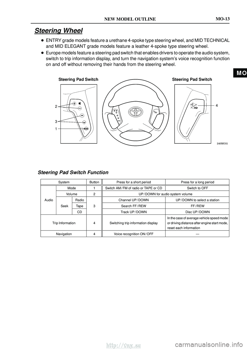
Steering Pad SwitchSteering Pad Switch
1 3 2 4
MO-13
Steering Wheel
�
ENTRY grade models feature a urethane 4-spoke type steering wheel, and MID T\
ECHNICAL
and MID ELEGANT grade models feature a leather 4-spoke type steering whe\
el.
� Europe models feature a steering pad switch that enables drivers to oper\
ate the audio system,
switch to trip information display, and turn the navigation system's voice recognition function
on and off without removing their hands from the steering wheel.
Steering Pad Switch Function
System ButtonPress for a short period Press for a long period
Mode 1 Switch AM / FM of radio or TAPE or CD Switch to OFF
Volume 2 UP / DOWN for audio system volume
Audio Radio Channel UP / DOWN UP / DOWN to select a station
Seek Tape 3
Search FF / REW FF / REW
CD Track UP / DOWN Disc UP / DOWN
Trip Information 4 Switching trip information display In the case of average vehicle speed mode
or driving distance after engine start mode,
reset each information
Navigation 4Voice recognition ON / OFF Ð
http://vnx.su
Page 18 of 2234
MO
NEW MODEL OUTLINE
�������
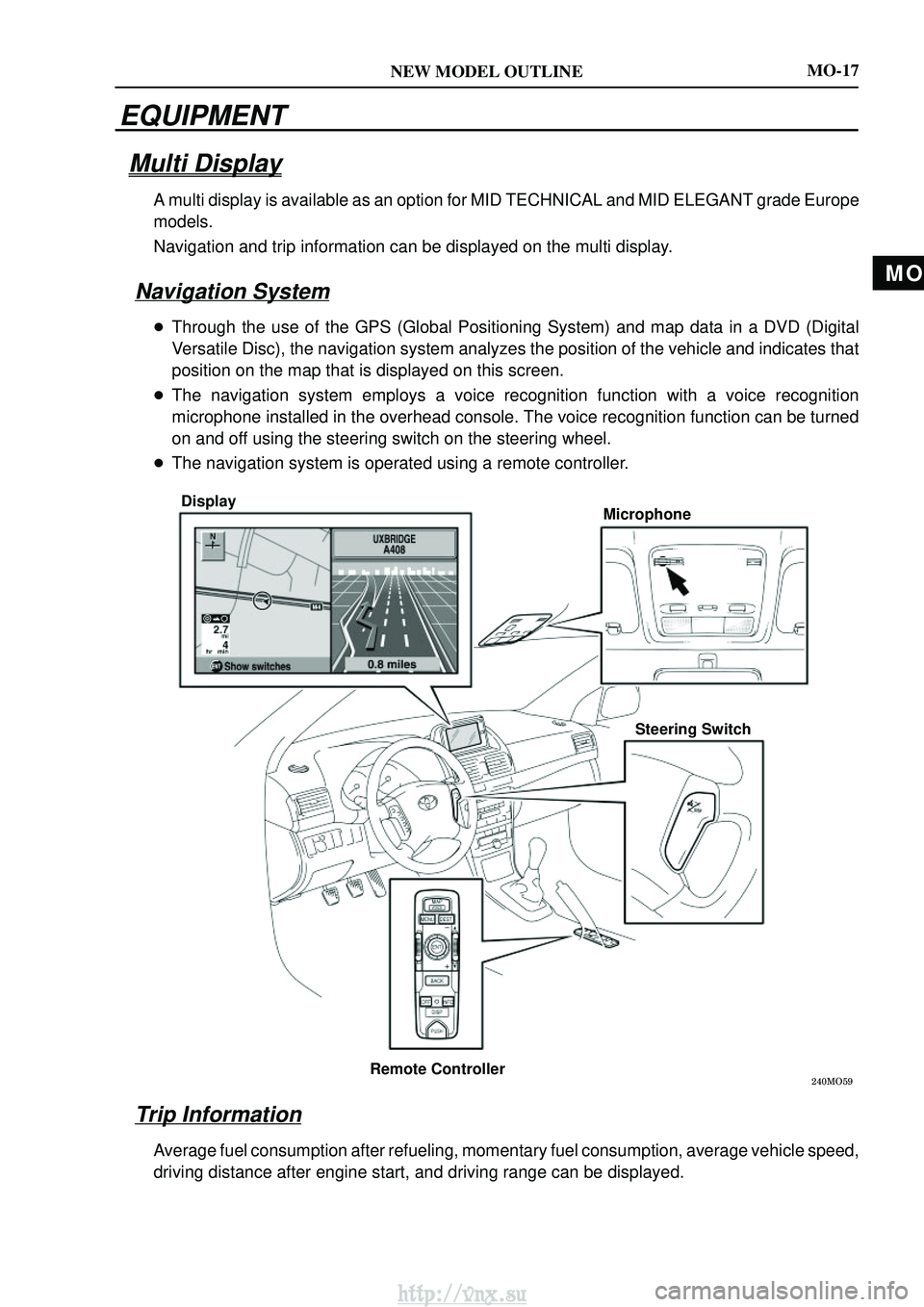
DisplayMicrophone
Steering Switch
Remote Controller
MO-17
EQUIPMENT
Multi Display
A multi display is available as an option for MID TECHNICAL and MID ELEG\
ANT grade Europe
models.
Navigation and trip information can be displayed on the multi display.
Navigation System
� Through the use of the GPS (Global Positioning System) and map data in a DVD \
(Digital
Versatile Disc), the navigation system analyzes the position of the vehi\
cle and indicates that
position on the map that is displayed on this screen.
� The navigation system employs a voice recognition function with a voice \
recognition
microphone installed in the overhead console. The voice recognition function can b\
e turned
on and off using the steering switch on the steering wheel.
� The navigation system is operated using a remote controller.
Trip Information
Average fuel consumption after refueling, momentary fuel consumption, ave\
rage vehicle speed,
driving distance after engine start, and driving range can be displayed.\
http://vnx.su
Page 31 of 2234
MO
NEW MODEL OUTLINEMO-29
�
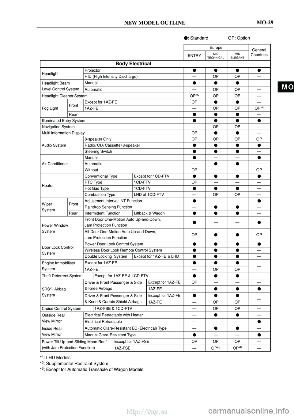
: Standard OP: Option
EuropeGeneral
ENTRYMID
TECHNICALMID
ELEGANTGeneralCountries
Body Electrical
HeadlightProjector����HeadlightHID (High lntensity Discharge)ÐOPOPÐ
Headlight BeamManual���Ð
Level Control SystemAutomaticÐOPOPÐ
Headlight Cleaner SystemOP*5OPOPÐ
FrontExcept for 1AZ-FEOP��Ð
Fog LightFront1AZ-FEÐOPOPOP*4
Rear���Ð
Illuminated Entry System����
Navigation SystemÐOPOPÐ
Multi information DisplayOP��Ð
8-speaker OnlyOPOPOPOP
Audio SystemRadio / CD / Cassette / 8-speaker����
Steering Switch���Ð
Manual�ÐÐ�
Air ConditionerAutomaticÐ��Ð
WithoutOPÐÐOP
Conventional TypeExcept for 1CD-FTV����
HeaterPTC Type1CD-FTVOPÐÐÐHeaterHot Gas Type1CD-FTV���Ð
Combustion TypeLHD of 1CD-FTVÐOPOPÐ
WiperFrontAdjustment Interval INT Function�ÐÐ�Wiper
SystemFrontRaindrop Sensing FunctionÐ��ÐSystemRearIntermittent FunctionLiftback & Wagon���Ð
Power Window
Front Door One-Motion Auto Up-and-Down,
Jam Protection Function�ÐÐ�
SystemAll-Door One-Motion Auto Up-and-Down,
Jam Protection FunctionOP��OP
Door Lock ControlPower Door Look Control System����Door Lock Control
SystemWireless Door Look Remote Control System���ÐSystemDouble Locking SystemExcept for 1AZ-FE & LHD���Ð
Engine ImmobiliserExcept for 1AZ-FE���
System1AZ-FEÐOPOPÐ
Theft Deterrent SystemExcept for 1AZ-FE & 1CD-FTV���Ð
5
Driver & Front Passenger & SideExcept for 1AZ-FEOPÐÐÐ
SRS*5 Airbag& Knee Airbags1AZ-FE���
SystemDriver & Front Passenger & SideExcept for 1AZ-FE���
& Knee & Curtain Shield Airbags1AZ-FEÐOPOPÐ
Cruise Control System1AZ-FSE & 1CD-FTVÐOPOPÐ
Outside RearElectrical Retractable with HeaterÐ��Ð
View MirrorElectrical RetractableÐÐÐ�
Inside RearAutomatic Glare-Resistant EC (Electrical) TypeÐ��Ð
View MirrorManual Glare-Resistant Type�ÐÐ�
Power Tilt Up-and-Sliding Moon RoofExcept for 1AZ-FSEOPOPOPÐ
(with Jam Protection Function)1AZ-FSEÐOP*6OP*6Ð
*4: LHD Models
*5: Supplemental Restraint System
*6: Except for Automatic Transaxle of Wagon Models
http://vnx.su
Page 56 of 2234
010B6±13
±
INTRODUCTIONHOW TO TROUBLESHOOT ECU CONTROLLED
SYSTEMS01±21
AVENSIS REPAIR MANUAL (RM1018E)
HOW TO TROUBLESHOOT ECU CONTROLLED SYSTEMS
GENERAL INFORMATION
There are many ECU controlled systems used in the AVENSIS. In general, ECU controlled system are con-
sidered to be very intricate and require a high level of technical knowledge an\
d expert skill to troubleshoot.
The fact is, however, that if you proceed by inspecting the circuits one by one, troubleshoo\
ting of these sys-
tems is not complex. If you have adequate understanding of the system and ba\
sic knowledge of electricity,
the problem can be accurately diagnosed and fixed. This manual is design\
ed based on the above principle
to help service technicians perform accurate and effective troubleshooting, and is compiled for the following
major ECU controlled systems:
The troubleshooting procedures are described on the following pages.
SystemPage
1. SFI System [1ZZ±FE, 3ZZ±FE]05±1
2. SFI System [1AZ±FE]05±143
3. SFI System [1AZ±FSE]05±290
4. ECD System [1CD±FTV]05±523
5. ABS with EBD System05±696
6. ABS with EBD & BA & TRC & VSC System05±752
7. Electronic Controlled Automatic Transmission [ECT] [U241 (1AZ±FE)]05±856
8. Electronic Controlled Automatic Transmission [ECT] [U241 (1AZ±FSE)]05±915
9. Electronic Controlled Automatic Transmission [ECT] [U341]05±980
10.Electronic Motor Power Steering System05±1042
11. Air Conditioning System05±1088
12.Combustion Type Power Heater System05±1161
13.Supplemental Restraint System05±1181
14.Audio System05±1393
15.Navigation System05±1435
16.Combination Meter05±1497
17.Power Door Lock Control System05±1534
18.Wireless Door Lock Control System05±1568
19.Key Reminder Warning System05±1586
20.Engine Immobiliser System05±1599
21.Theft Deterrent System05±1627
22.Multiplex Communication System05±1654
23.Cruise Control System05±1697
FOR USING HAND±HELD TESTER
�Before using the tester, the tester's operator manual should be read thoroughly.
�If the tester cannot communicate with the ECU controlled systems when you \
have connected the cable
of tester to the DLC3, turned the ignition switch ON and operated the test\
er, there is a problem on the
vehicle side or tester side.
(1) If the communication is normal when the tester is connected to another veh\
icle, inspect the diag-
nosis data link line (Bus �line) or ECU power circuit of the vehicle.
(2) If the communication is still impossible when the tester is connected to a\
nother vehicle, the prob- lem is probably in the tester itself, so perform the Self Test procedures outlined in the Tester Oper-
ator 's Manual.
http://vnx.su
Page 95 of 2234
022KX±01
±
PREPARATION AUDIO & VISUAL SYSTEM
02±55
AVENSIS REPAIR MANUAL (RM1018E)
AUDIO & VISUAL SYSTEM
PREPARATION
Recomended Tools
09042±00010Torx Socket T30NAVIGATION ANTENNA ASSY
09042±00030Torx Socket T20CIGARETTE LIGHTER ASSY
09050±00032Air DrillFRONT NO.1 SPEAKER ASSY
REAR SPEAKER ASSY
(09050±00210)Chuck SetFRONT NO.1 SPEAKER ASSY
REAR SPEAKER ASSY
(09050±00220)HandleFRONT NO.1 SPEAKER ASSY
REAR SPEAKER ASSY
09050±20010Air RiveterFRONT NO.1 SPEAKER ASSY
REAR SPEAKER ASSY
(09050±02010)Dust CapFRONT NO.1 SPEAKER ASSY
REAR SPEAKER ASSY
(09050±02020)Nose Piece No.1FRONT NO.1 SPEAKER ASSY
REAR SPEAKER ASSY
09060±60350Revet CutterFRONT NO.1 SPEAKER ASSY
REAR SPEAKER ASSY
09070±20010Moulding RemoverRADIO RECEIVER ASSY
ANTENNA CORD SUB±ASSY
POWER POINT SOCKET ASSY
NAVIGATION ANTENNA ASSY
ANTENNA CORD SUB±ASSY NO.3
AMPLIFIER ANTENNA
ASSY(LIFTBACK MODELS)
AMPLIFIER ANTENNA ASSY(SEDAN
MODELS)
AMPLIFIER ANTENNA
ASSY(WAGON MODELS)
Equipment
Torque wrench
http://vnx.su
Page 1544 of 2234
670SC±03
67±16
±
AUDIO & VISUAL SYSTEM AMPLIFIER ANTENNA ASSY (SEDAN MODELS)
AVENSIS REPAIR MANUAL (RM1018E)
AMPLIFIER ANTENNA ASSY (SEDAN MODELS)
REPLACEMENT
1.DISCONNECT BATTERY NEGATIVE TERMINAL (See page 60±1)
2.REMOVE INSTRUMENT CLUSTER FINISH PANEL GARNISH NO.2 (See page 71±11)
3. REMOVE INSTRUMENT PANEL REGISTER ASSY CTR (W/ NAVIGATION SYSTEM) (See page 67±6)
4.REMOVE SHIFT LEVER KNOB SUB±ASSY (M/T TRANSAXLE) (See page 41±11)
5.REMOVE CONSOLE PANEL SUB±ASSY UPPER (See page 71±11)
6.REMOVE RADIO RECEIVER ASSEMBLY W/BRACKET (See page 67±5)
7.REMOVE CONSOLE BOX ASSY RR (See page 71±11)
8.REMOVE HEATER TO REGISTER DUCT NO.2 (See page 71±11)
9.REMOVE FRONT SEAT ASSY RH (See page POWER SEAT 72±11, MANUAL SEAT72±16)
10.REMOVE FRONT DOOR SCUFF PLATE RH (See page 76±36)
11.REMOVE REAR DOOR SCUFF PLATE RH (See page 76±36)
12.REMOVE COWL SIDE TRIM BOARD RH (See page 76±36)
13.REMOVE FRONT DOOR OPENING TRIM WEATHERSTRIP RH (See page 76±36)
14.REMOVE REAR DOOR OPENING TRIM WEATHERSTRIP RH (See page 76±36)
15.REMOVE REAR SEAT CUSHION ASSEMBLY (See page 72±32)
16.REMOVE REAR SEATBACK ASSY (See page 40/60 FOLDING 72±27, UNITED FIXED 72±32)
17.REMOVE ROOF SIDE GARNISH INNER RH (See page 76±36)
18. REMOVE FLOOR CARPET ASSY FRONT
http://vnx.su
Page 1545 of 2234
I35246Clamps
w/ Navigation:
w/ Navigation:
±
AUDIO & VISUAL SYSTEM AMPLIFIER ANTENNA ASSY (SEDAN MODELS)
67±17
AVENSIS REPAIR MANUAL (RM1018E)
19. REMOVE AMPLIFIER ANTENNA ASSY
(a) Disconnect the connectors.
(b) w/ Navigation:
Remove the 2 bolts, nut and screw.
w/o Navigation:
Remove the 2 bolts and nut.
(c) w/ Navigation:
Remove the 11 clamps and amplifier antenna assy.
w/o Navigation:
Remove the 10 clamps and amplifier antenna assy.
http://vnx.su
Page 1546 of 2234
67±18
±
AUDIO & VISUAL SYSTEMAMPLIFIER ANTENNA ASSY(SEDAN MODELS)
AVENSIS REPAIR MANUAL (RM1018E)
20.INSTALL AMPLIFIER ANTENNA ASSY
(a)Install the 2 bolts. Torque: 7.0 N �m (71 kgf�cm, 62 in. �lbf)
(b)w/ Navigation: Install the nut and screw.
w/o Navigation:
Install the nut.
(c)w/ Navigation: Install the 11 clamps and the amplifier antenna assy.
w/o Navigation:
Install the 10 clamps and the amplifier antenna assy.
(d)Connect the connectors.
21.REMOVE REAR SEAT CUSHION ASSEMBLY (See page 72±32)
22.REMOVE REAR SEATBACK ASSY (See page 40/60 FOLDING 72±27, UNITED FIXED 72±32)
23.REMOVE FRONT SEAT ASSY RH (See page POWER SEAT 72±11, MANUAL SEAT 72±16)
http://vnx.su