Page 1666 of 2234
B70314
Slide MotorLifter MotorSlide MotorFront Vertical Motor
Reclining Motor
Reclining Motor
Power Seat Switch Assy
(Lumbar Support)
Front Power Seat Switch RH
Lumbar Support Adjuster Motor
Front Power Seat Switch LH
72±2
±
SEAT FRONT POWER SEAT CONTROL SYSTEM
AVENSIS REPAIR MANUAL (RM1018E)
http://vnx.su
Page 1667 of 2234
720J2±01
±
SEAT FRONT POWER SEAT CONTROL SYSTEM
72±3
AVENSIS REPAIR MANUAL (RM1018E)
PROBLEM SYMPTOMS TABLE
SymptomSuspected AreaSee Page
Power seat does not operate
1. Front power seat switch
2. PWR SEAT H±fuse
3. Wire harness72±6
68±1
�
Only slide operation function does not operate
1. Front power seat switch
2. Slide motor
3. Wire harness����
���� �
Only front vertical operation function does not operate
(Driver seat only)1. Front power seat switch
2. Front vertical motor
3. Wire harness����
�����
Only lifter operation function does not operate
(Driver seat only)1. Front power seat switch
2. Lifter motor
3. Wire harness����
�����
Only reclining operation function does not operate
1. Front power seat switch
2. Reclining motor
3. Wire harness����
�����
Only lumbar support operation function does not operate
(Driver seat only)1. Power seat switch assy (Lumbar support)
2. Lumbar support adjuster motor
3. Wire harness����
�����
http://vnx.su
Page 1668 of 2234
720J3±01
B67823
Reclining Function
Lumbar Support
Function
Sliding Function
Front Vertical
Function
Lifter Function
72±4
±
SEAT FRONT POWER SEAT CONTROL SYSTEM
AVENSIS REPAIR MANUAL (RM1018E)
ON±VEHICLE INSPECTION
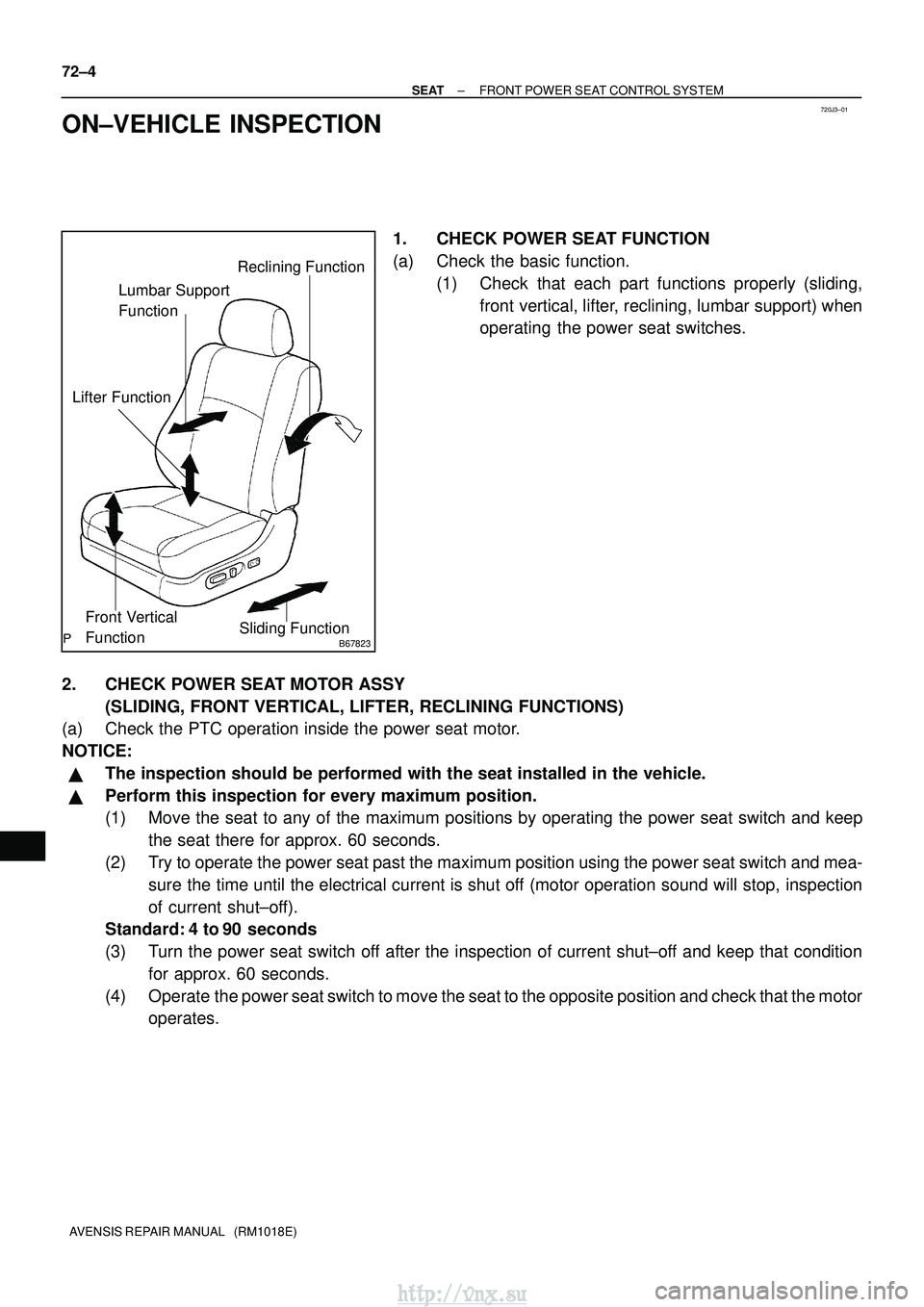
1. CHECK POWER SEAT FUNCTION
(a) Check the basic function. (1) Check that each part functions properly (sliding,front vertical, lifter, reclining, lumbar support) when
operating the power seat switches.
2. CHECK POWER SEAT MOTOR ASSY (SLIDING, FRONT VERTICAL, LIFTER, RECLINING FUNCTIONS)
(a) Check the PTC operation inside the power seat motor.
NOTICE:
�The inspection should be performed with the seat installed in the vehicl\
e.
�Perform this inspection for every maximum position.
(1) Move the seat to any of the maximum positions by operating the power sea\
t switch and keep
the seat there for approx. 60 seconds.
(2) Try to operate the power seat past the maximum position using the power s\
eat switch and mea- sure the time until the electrical current is shut off (motor operation sound will stop, inspection
of current shut±off).
Standard: 4 to 90 seconds
(3) Turn the power seat switch off after the inspection of current shut±off and keep that condition
for approx. 60 seconds.
(4) Operate the power seat switch to move the seat to the opposite position and che\
ck that the motor operates.
http://vnx.su
Page 1669 of 2234
±
SEAT FRONT POWER SEAT CONTROL SYSTEM
72±5
AVENSIS REPAIR MANUAL (RM1018E)
3. CHECK LUMBAR SUPPORT ADJUSTER ASSY LH
(a) Inspect the PTC operation inside the lumber support motor.
NOTICE:
The inspection should be performed with the seat installed to the vehicl\
e.
(1) Move the lumbar support to either the foremost or rearmost position by opera\
ting the lumbar sup-port switch and keep it there for approx. 60 seconds.
(2) Try to move the lumbar support past the maximum position using the switch\
and measure the
time until the electrical current is shut off (motor operation sound will stop, inspection of current
shut±off).
Standard: 4 to 90 seconds
(3) Turn the lumbar support switch off after the inspection of current shut±off and keep that condition for approx. 60 seconds.
(4) Operate the lumbar support switch to move the lumbar support to the opposite po\
sition and check that the motor operates.
http://vnx.su
Page 1671 of 2234
B65447
Reclining Switch
Slide Switch
Front Power Seat Switch
B65442
Power Seat Switch Assy
(Lumbar Support)
±
SEAT FRONT POWER SEAT CONTROL SYSTEM
72±7
AVENSIS REPAIR MANUAL (RM1018E)
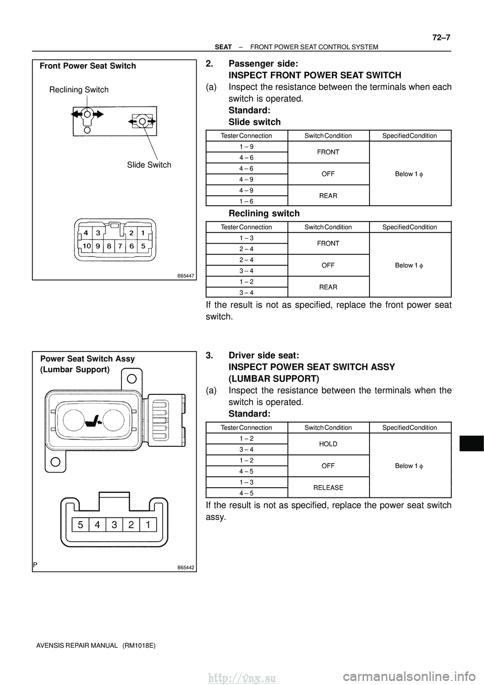
2. Passenger side:
INSPECT FRONT POWER SEAT SWITCH
(a) Inspect the resistance between the terminals when each
switch is operated.
Standard:
Slide switch
Tester ConnectionSwitch ConditionSpecified Condition
1 ± 9FRONT4 ± 6FRONT
4 ± 6OFFBelow 1 �4 ± 9OFFBelow 1 �
4 ± 9REAR1 ± 6REAR
Reclining switch
Tester ConnectionSwitch ConditionSpecified Condition
1 ± 3FRONT2 ± 4FRONT
2 ± 4OFFBelow 1�3 ± 4OFFBelow 1 �
1 ± 2REAR3 ± 4REAR
If the result is not as specified, replace the front power seat
switch.
3. Driver side seat:
INSPECT POWER SEAT SWITCH ASSY
(LUMBAR SUPPORT)
(a) Inspect the resistance between the terminals when the
switch is operated.
Standard:
Tester ConnectionSwitch ConditionSpecified Condition
1 ± 2HOLD3 ± 4HOLD
1 ± 2OFFBelow 1 �4 ± 5OFFBelow 1 �
1 ± 3RELEASE4 ± 5RELEASE
If the result is not as specified, replace the power seat switch
assy.
http://vnx.su
Page 1673 of 2234
B65859
Clockwise
Counter±
clockwise
Reclining Motor
Driving Axis
B65448
Clockwise
Driving Axis Counter±clockwise Lumbar Support
Adjuster Motor
±
SEAT FRONT POWER SEAT CONTROL SYSTEM
72±9
AVENSIS REPAIR MANUAL (RM1018E)
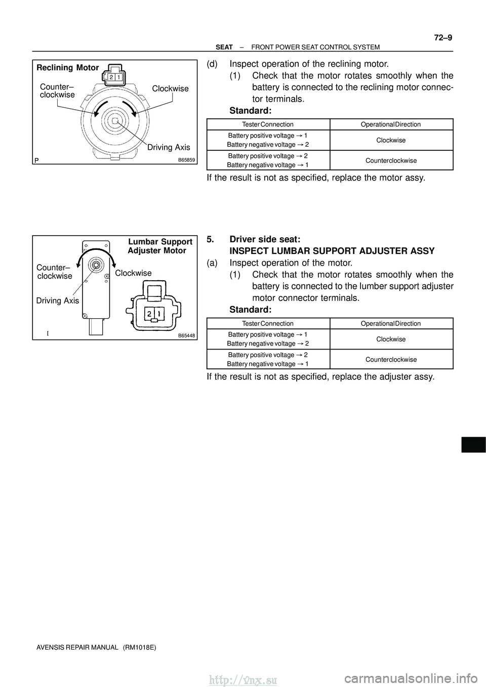
(d) Inspect operation of the reclining motor.
(1) Check that the motor rotates smoothly when thebattery is connected to the reclining motor connec-
tor terminals.
Standard:
Tester ConnectionOperational Direction
Battery positive voltage �1
Battery negative voltage �2Clockwise
Battery positive voltage �2
Battery negative voltage �1Counterclockwise
If the result is not as specified, replace the motor assy.
5. Driver side seat:
INSPECT LUMBAR SUPPORT ADJUSTER ASSY
(a) Inspect operation of the motor. (1) Check that the motor rotates smoothly when thebattery is connected to the lumber support adjuster
motor connector terminals.
Standard:
Tester ConnectionOperational Direction
Battery positive voltage �1
Battery negative voltage �2Clockwise
Battery positive voltage �2
Battery negative voltage �1Counterclockwise
If the result is not as specified, replace the adjuster assy.
http://vnx.su
Page 1678 of 2234
720J5±01
B70315
Headrest Support
Power Seat Switch Assy
Power Seat Switch Knob
Front Seat Inner Belt Assy LH
Front Seat Headrest Assy
�
Hog Ring
Separate Type Front Seatback Cover
� Hog Ring
Front Seatback Pad
Seat Cushion Pad Reclining Adjuster Inside Cover RH
Reclining Adjuster Inside Cover LH
Vertical Adjuster Bracket Cover Outer
Wire Harness Connector
Front Seat Cushion Shield LH Headrest Support
Lumbar Support Adjuster Assy Seat Track Cover
42 (428, 31)
6.0 (61, 53 in.�lbf)
: Specified torqueN �m (kgf� cm, ft�lbf)
� Non±reusable part
Front Power Seat Switch
37 (375, 27)
Clip
Clip
8.0 (82, 71 in.
�lbf)
Seat Position Airbag Sensor
Bush
37 (375, 27)37 (375, 27)
Front Seat Cushion Shield
Front Seat Cushion Shield Inner LH
4.5 (46, 40 in.
�lbf)
4.0 (41, 35 in. �lbf)
2.5 (25, 22 in. �lbf)
2.5 (25, 22 in. �lbf)
25 (255, 18)
3.5 (36, 31 in. �lbf)
25 (255, 18)
Power Seat Motor Assy (Lifter)
(Front Vertical) Power Seat Motor Assy
(Reclining)Power Seat Motor Assy
Power Seat Motor Assy Front Seat Adjuster Assy LH
Separate Type Front Seat Cushion Cover
Separate Type Front
Vertical Adjuster
Inner No.1 LH
(w/ Seat Heater)
(w/ Seat Heater)
Seat Heater Control Sub±assy
Bracket Cover Inner
(Slide)
72±10
±
SEAT FRONT SEAT ASSEMBLY LH (POWER SEAT TYPE)
AVENSIS REPAIR MANUAL (RM1018E)
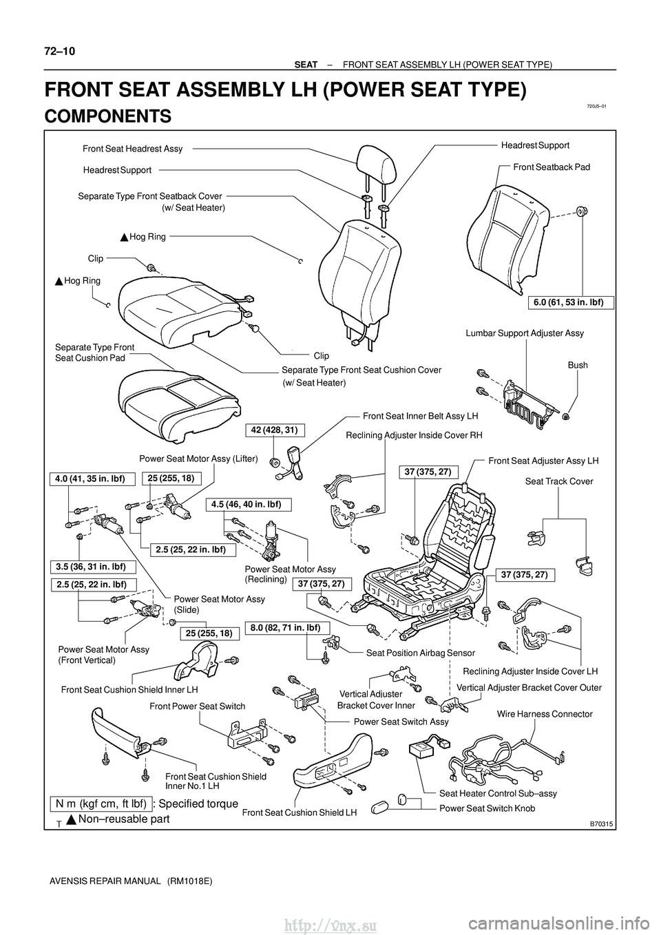
FRONT SEAT ASSEMBLY LH (POWER SEAT TYPE)
COMPONENTS
http://vnx.su
Page 1680 of 2234
B70317
ClawClip
B60977
72±12
±
SEAT FRONT SEAT ASSEMBLY LH (POWER SEAT TYPE)
AVENSIS REPAIR MANUAL (RM1018E)
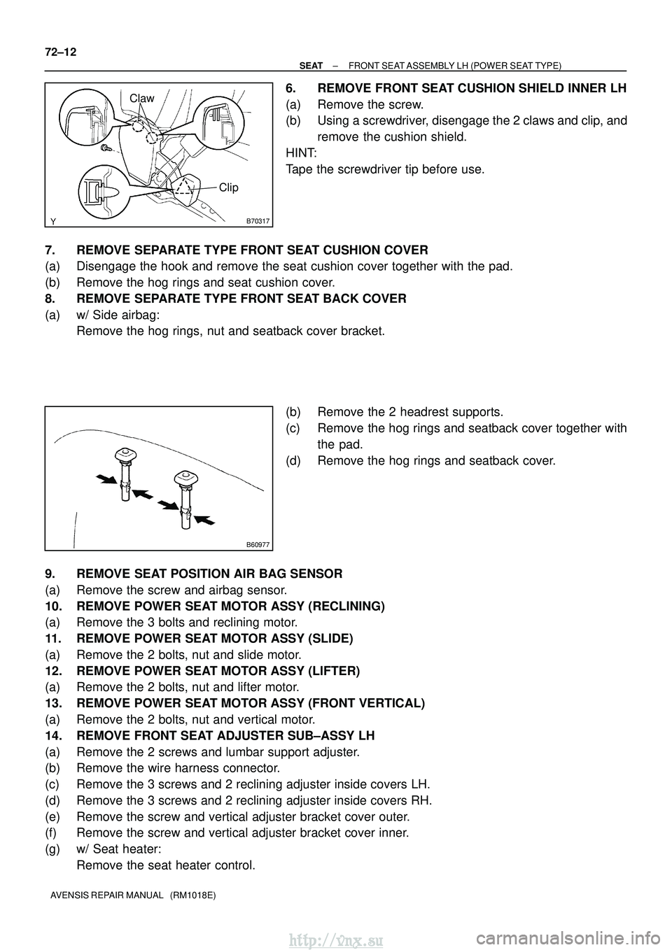
6. REMOVE FRONT SEAT CUSHION SHIELD INNER LH
(a) Remove the screw.
(b) Using a screwdriver, disengage the 2 claws and clip, and remove the cushion shield.
HINT:
Tape the screwdriver tip before use.
7. REMOVE SEPARATE TYPE FRONT SEAT CUSHION COVER
(a) Disengage the hook and remove the seat cushion cover together with the p\
ad.
(b) Remove the hog rings and seat cushion cover.
8. REMOVE SEPARATE TYPE FRONT SEAT BACK COVER
(a) w/ Side airbag: Remove the hog rings, nut and seatback cover bracket.
(b) Remove the 2 headrest supports.
(c) Remove the hog rings and seatback cover together withthe pad.
(d) Remove the hog rings and seatback cover.
9. REMOVE SEAT POSITION AIR BAG SENSOR
(a) Remove the screw and airbag sensor.
10. REMOVE POWER SEAT MOTOR ASSY (RECLINING)
(a) Remove the 3 bolts and reclining motor.
11. REMOVE POWER SEAT MOTOR ASSY (SLIDE)
(a) Remove the 2 bolts, nut and slide motor.
12. REMOVE POWER SEAT MOTOR ASSY (LIFTER)
(a) Remove the 2 bolts, nut and lifter motor.
13. REMOVE POWER SEAT MOTOR ASSY (FRONT VERTICAL)
(a) Remove the 2 bolts, nut and vertical motor.
14. REMOVE FRONT SEAT ADJUSTER SUB±ASSY LH
(a) Remove the 2 screws and lumbar support adjuster.
(b) Remove the wire harness connector.
(c) Remove the 3 screws and 2 reclining adjuster inside covers LH.
(d) Remove the 3 screws and 2 reclining adjuster inside covers RH.
(e) Remove the screw and vertical adjuster bracket cover outer.
(f) Remove the screw and vertical adjuster bracket cover inner.
(g) w/ Seat heater: Remove the seat heater control.
http://vnx.su