Page 1120 of 2234

320VV±01
G23167
F08657
BoltSST
SST
Bolt
±
BRAKE SKID CONTROL SENSOR
32±61
AVENSIS REPAIR MANUAL (RM1018E)
SKID CONTROL SENSOR
REPLACEMENT
HINT:
Replace the RH side by using the same procedures as those for the LH side.
1. REMOVE REAR WHEEL
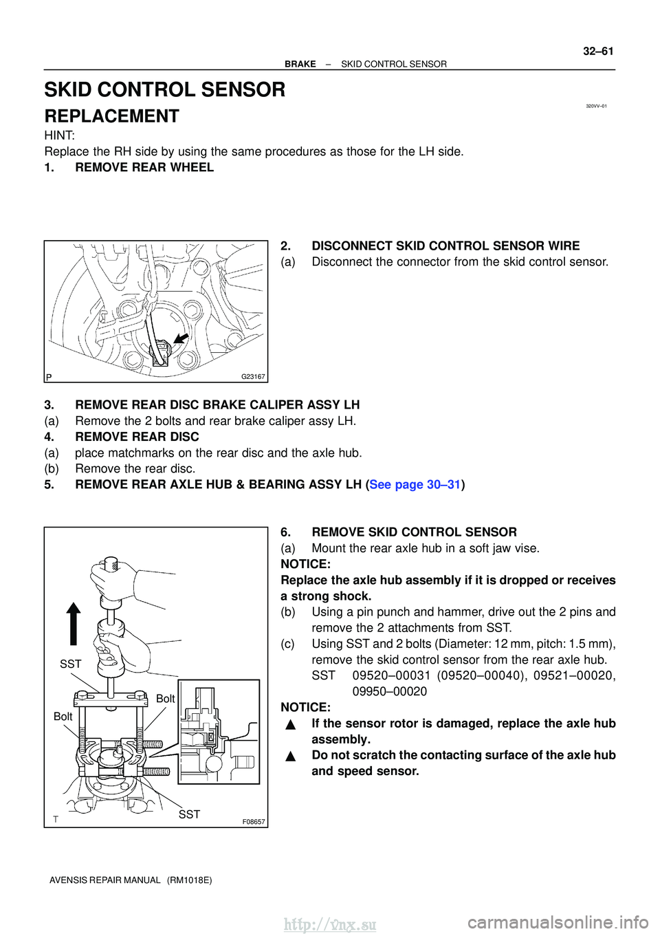
2. DISCONNECT SKID CONTROL SENSOR WIRE
(a) Disconnect the connector from the skid control sensor.
3. REMOVE REAR DISC BRAKE CALIPER ASSY LH
(a) Remove the 2 bolts and rear brake caliper assy LH.
4. REMOVE REAR DISC
(a) place matchmarks on the rear disc and the axle hub.
(b) Remove the rear disc.
5.REMOVE REAR AXLE HUB & BEARING ASSY LH (See page 30±31) 6. REMOVE SKID CONTROL SENSOR
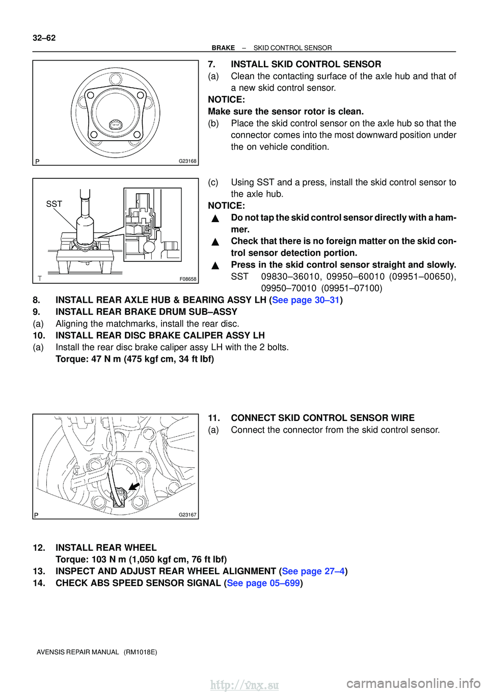
(a) Mount the rear axle hub in a soft jaw vise.
NOTICE:
Replace the axle hub assembly if it is dropped or receives
a strong shock.
(b) Using a pin punch and hammer, drive out the 2 pins andremove the 2 attachments from SST.
(c) Using SST and 2 bolts (Diameter: 12 mm, pitch: 1.5 mm), remove the skid control sensor from the rear axle hub.
SST 09520±00031 (09520±00040), 09521±00020, 09950±00020
NOTICE:
�If the sensor rotor is damaged, replace the axle hub
assembly.
�Do not scratch the contacting surface of the axle hub
and speed sensor.
http://vnx.su
Page 1121 of 2234

G23168
F08658
SST
G23167
32±62
±
BRAKE SKID CONTROL SENSOR
AVENSIS REPAIR MANUAL (RM1018E)
7. INSTALL SKID CONTROL SENSOR
(a) Clean the contacting surface of the axle hub and that of a new skid control sensor.
NOTICE:
Make sure the sensor rotor is clean.
(b) Place the skid control sensor on the axle hub so that the connector comes into the most downward position under
the on vehicle condition.
(c) Using SST and a press, install the skid control sensor to the axle hub.
NOTICE:
�Do not tap the skid control sensor directly with a ham-
mer.
�Check that there is no foreign matter on the skid con-
trol sensor detection portion.
�Press in the skid control sensor straight and slowly.
SST 09830±36010, 09950±60010 (09951±00650), 09950±70010 (09951±07100)
8.INSTALL REAR AXLE HUB & BEARING ASSY LH (See page 30±31)
9. INSTALL REAR BRAKE DRUM SUB±ASSY
(a) Aligning the matchmarks, install the rear disc.
10. INSTALL REAR DISC BRAKE CALIPER ASSY LH
(a) Install the rear disc brake caliper assy LH with the 2 bolts. Torque: 47 N �m (475 kgf� cm, 34 ft�lbf)
11. CONNECT SKID CONTROL SENSOR WIRE
(a) Connect the connector from the skid control sensor.
12. INSTALL REAR WHEEL Torque: 103 N� m (1,050 kgf�cm, 76 ft �lbf)
13.INSPECT AND ADJUST REAR WHEEL ALIGNMENT (See page 27±4)
14.CHECK ABS SPEED SENSOR SIGNAL (See page 05±699)
http://vnx.su
Page 1128 of 2234
32092±05
G24249
Oil Hose
Vacuum Hose O±Ring
Vacuum Pump Assy
Vacuum Hose
Check Valve Sub±assy Vacuum Pump Union
Gasket
Straight Pin
Vacuum Pump End Cover
Snap Ring
Coupling Vaccup Pump Housing
Vacuum pump Blade A Straight Pin
N�m (kgf� cm, ft�lbf) : Specified torque
� Non±reusable part �
O±Ring
�
� Gasket
�
Gasket
�
�
O±Ring
�
Union bolt
7.8 (80, 69 in.� lbf)
7.8 (80, 69 in.�lbf)
7.8 (80, 69 in. �lbf)
14 (140, 10)
21 (214, 15)
21 (214, 15)
Air Cleaner Cap Sub±assy
74 (750, 54)
Connector
Vacuum pump Rotor
32±34
±
BRAKE VACUUM PUMP ASSY (1CD±FTV)
AVENSIS REPAIR MANUAL (RM1018E)
COMPONENTS
http://vnx.su
Page 1130 of 2234

F08969
F08970
F08971
F08972
Snap Ring
F45365
Vacuum Pump Housing
Vacuum Pump End Cover
32±36
±
BRAKE VACUUM PUMP ASSY (1CD±FTV)
AVENSIS REPAIR MANUAL (RM1018E)
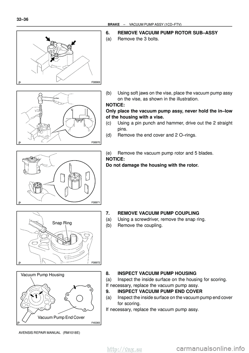
6. REMOVE VACUUM PUMP ROTOR SUB±ASSY
(a) Remove the 3 bolts.
(b) Using soft jaws on the vise, place the vacuum pump assy on the vise, as shown in the illustration.
NOTICE:
Only place the vacuum pump assy, never hold the in±low
of the housing with a vise.
(c) Using a pin punch and hammer, drive out the 2 straight pins.
(d) Remove the end cover and 2 O±rings.
(e) Remove the vacuum pump rotor and 5 blades.
NOTICE:
Do not damage the housing with the rotor.
7. REMOVE VACUUM PUMP COUPLING
(a) Using a screwdriver, remove the snap ring.
(b) Remove the coupling.
8. INSPECT VACUUM PUMP HOUSING
(a) Inspect the inside surface on the housing for scoring.
If necessary, replace the vacuum pump assy.
9. INSPECT VACUUM PUMP END COVER
(a) Inspect the inside surface on the vacuum pump end cover for scoring.
If necessary, replace the vacuum pump assy.
http://vnx.su
Page 1131 of 2234

F05383
Air
Hose Side Vacuum Pump Side
Air
F08981
F08982
New O±Ring
F08970
±
BRAKE VACUUM PUMP ASSY (1CD±FTV)
32±37
AVENSIS REPAIR MANUAL (RM1018E)
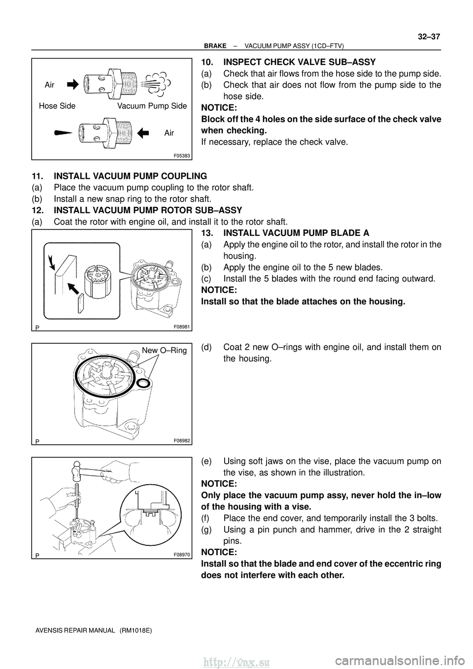
10. INSPECT CHECK VALVE SUB±ASSY
(a) Check that air flows from the hose side to the pump side.
(b) Check that air does not flow from the pump side to the
hose side.
NOTICE:
Block off the 4 holes on the side surface of the check valve
when checking.
If necessary, replace the check valve.
11. INSTALL VACUUM PUMP COUPLING
(a) Place the vacuum pump coupling to the rotor shaft.
(b) Install a new snap ring to the rotor shaft.
12. INSTALL VACUUM PUMP ROTOR SUB±ASSY
(a) Coat the rotor with engine oil, and install it to the rotor shaft. 13. INSTALL VACUUM PUMP BLADE A
(a) Apply the engine oil to the rotor, and install the rotor in the
housing.
(b) Apply the engine oil to the 5 new blades.
(c) Install the 5 blades with the round end facing outward.
NOTICE:
Install so that the blade attaches on the housing.
(d) Coat 2 new O±rings with engine oil, and install them on the housing.
(e) Using soft jaws on the vise, place the vacuum pump on the vise, as shown in the illustration.
NOTICE:
Only place the vacuum pump assy, never hold the in±low
of the housing with a vise.
(f) Place the end cover, and temporarily install the 3 bolts.
(g) Using a pin punch and hammer, drive in the 2 straight pins.
NOTICE:
Install so that the blade and end cover of the eccentric ring
does not interfere with each other.
http://vnx.su