Page 14 of 2234

NEW MODEL OUTLINE
����\b��
����\b��
����\b��
Power Lumber Support
Power Seat
Cushion Front Tilt
Power Seat
Seat Slide
Power Seat Manual Seat
Seat Reclining
Power SeatVertical Lifter
Power Seat Manual Seat
Manual Seat
MO-14
Seat
� The seat features a high-quality
finish with an elegant stitch.
� Leather seats are available as an
option for MID TECHNICAL and
MID ELEGANT grade with the
1AZ-FSE or 1CD-FTV engine
models.
Front Seat
�Power seats are available as a set option with leather seats.
� The adjustment lever of manual seats now features a ratchet mechanism fo\
r ease of
operation.
� A seat heater is available as an option for Europe LHD models.
Front Seat Function
ItemManual Seat Power SeatItemDriver'sPassenger's Driver'sPassenger's
Seat Slide 240 mm: 15 mm x 16-Steps 240 mm: Step Less
Seat Reclining 48 �: Step Less (Lever 1 operation: Max. 1 �)4 8�: Step Less
Vertical Lifter 45 mm: Step Less (Lever 1
operation: Max. 2.5 mm) Ð
50 mm: Step Less Ð
Cushion Front Tilt ÐÐ34 mm: Step Less Ð
Power Lumber Support ÐÐStandard Ð
Headrest Vertical Adjuster 60 mm: 15 mm x 4-Steps
Headrest Swing Adjuster 18.5 �: Standard (MID TECHNICAL and MID ELEGANT grade for Europe and General Countries)
Seat Heater Option: LHD for Europe
http://vnx.su
Page 15 of 2234
MO
NEW MODEL OUTLINE
����\b������\b������\b��
Fixed Seat60:40 Separate Seat Back 60:40 Separate Seat
����\b��
����\b��
Sedan Model Liftback and Wagon Model
CRS Tether Anchor Bracket
CRS ISO-FIX Bar CRS Tether Anchor Bracket
CRS ISO-FIX Bar
����\b��
����\b��
Sedan Model Liftback ModelGrocery Bag
Hook (Both Side)
Tie-down
Hook
Auxiliary Box
Tie-down
HookTool Box
Tie-down Hook Auxiliary Box Grocery Bag Hook (Both Side)
Tie-down
Hook
Tool Box Tie-down
HookAuxiliary
Box
MO-15
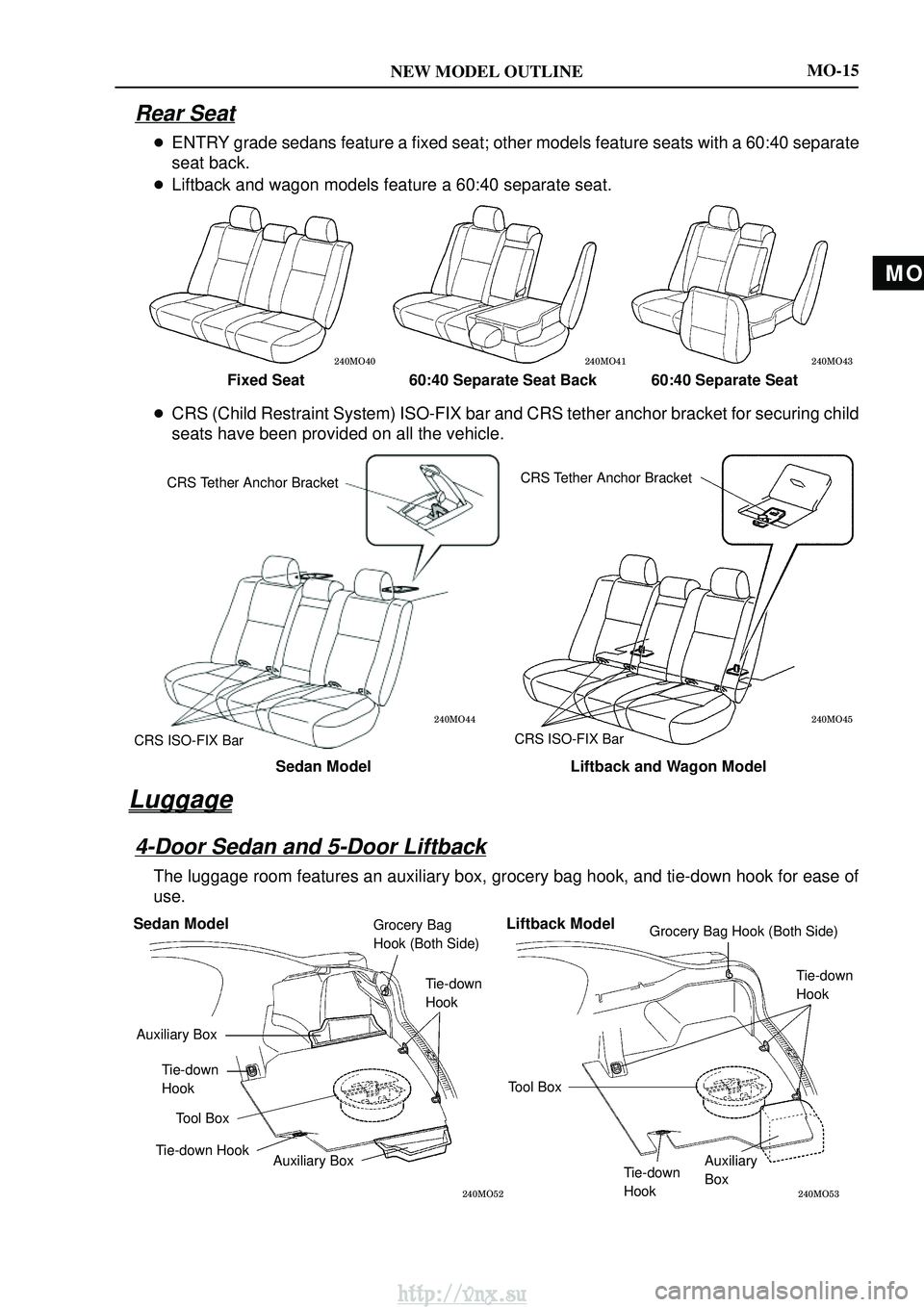
Rear Seat
�
ENTRY grade sedans feature a fixed seat; other models feature seats with a 6\
0:40 separate
seat back.
� Liftback and wagon models feature a 60:40 separate seat.
� CRS (Child Restraint System) ISO-FIX bar and CRS tether anchor bracket\
for securing child
seats have been provided on all the vehicle.
Luggage
4-Door Sedan and 5-Door Liftback
The luggage room features an auxiliary box, grocery bag hook, and tie-do\
wn hook for ease of
use.
http://vnx.su
Page 16 of 2234
MO
NEW MODEL OUTLINE
����\b������\b������\b��
Fixed Seat60:40 Separate Seat Back 60:40 Separate Seat
����\b��
����\b��
Sedan Model Liftback and Wagon Model
CRS Tether Anchor Bracket
CRS ISO-FIX Bar CRS Tether Anchor Bracket
CRS ISO-FIX Bar
����\b��
����\b��
Sedan Model Liftback ModelGrocery Bag
Hook (Both Side)
Tie-down
Hook
Auxiliary Box
Tie-down
HookTool Box
Tie-down Hook Auxiliary Box Grocery Bag Hook (Both Side)
Tie-down
Hook
Tool Box Tie-down
HookAuxiliary
Box
MO-15
Rear Seat
�
ENTRY grade sedans feature a fixed seat; other models feature seats with a 6\
0:40 separate
seat back.
� Liftback and wagon models feature a 60:40 separate seat.
� CRS (Child Restraint System) ISO-FIX bar and CRS tether anchor bracket\
for securing child
seats have been provided on all the vehicle.
Luggage
4-Door Sedan and 5-Door Liftback
The luggage room features an auxiliary box, grocery bag hook, and tie-do\
wn hook for ease of
use.
http://vnx.su
Page 28 of 2234
 Airbag System
�A newly developed SRS knee airbag")
NEW MODEL OUTLINE
�������
SRS Airbag
SRS Knee Airbag
�������
SRS Curtain Shield Airbag SRS Side Airbag
MO-26
SAFETY
SRS (Supplemental Restraint System) Airbag System
�A newly developed SRS knee airbag is standard equipment for the driver's seat on the new
Avensis.
� The SRS knee airbag is positioned in the lower part of the instrument pa\
nel on the driver's side
to receive the impact of the driver's lower body when he or she shifts forward in the event of
a frontal collision, contributing to prevention of secondary impact to t\
he lower body.
� Dual-stage SRS airbags are standard equipment for the driver and front p\
assenger seats. In
the event of a severe frontal collision, the airbags function with the s\
eat belts to help reduce
the impact on the driver's and front passenger's head and chest. The seat position sensor is
adopted only for the driver's seat to help the driver side SRS airbag deploy at the right moment.
� SRS side airbags (driver / front passenger seats) which help ease side\
impacts, are standard
equipment.
� SRS curtain shield airbags (front/rear seats) that help ease side impa\
cts are standard
equipment for all models except 1AZ-FE engine models. They are available as an op\
tion for
1AZ-FE engine models.
http://vnx.su
Page 404 of 2234

11±61
AVENSIS REPAIR MANUAL (RM1018E)
11.REMOVE NOZZLE HOLDER SEAL
(a)Using a screwdriver, pry out the 4 nozzle holder seals.
12.REMOVE CYLINDER")
A09656
A79144
A80110
±
FUELINJECTOR ASSY(1CD±FTV)
11±61
AVENSIS REPAIR MANUAL (RM1018E)
11.REMOVE NOZZLE HOLDER SEAL
(a)Using a screwdriver, pry out the 4 nozzle holder seals.
12.REMOVE CYLINDER HEAD COVER SUB±ASSY
(a)Remove the 10 bolts and the cylinder head cover.
13.REMOVE NOZZLE LEAKAGE PIPE ASSY
(a)Remove the union bolt and the 4 hollow screws, then re-
move the nozzle leakage pipe and the 5 gaskets.
NOTICE:
When removing then nozzle leakage pipe, place the shop
rag under the pipe to protect the cylinder head from the fuel
remaining inside the pipe.
14.REMOVE NOZZLE HOLDER CLAMP
(a)Remove the 4 bolts, 4 washers and 4 nozzle holder clamps.
15.REMOVE INJECTOR ASSY
(a)Remove the 4 injectors from the cylinder head.
(b)Remove the O±rings and back±up rings from each injector.
(c)Remove the 4 nozzle seats from the cylinder head.
16.REGISTRATION OF INJECTOR COMPENSATION CODE (See page 05±528)
HINT:
Each injector assembly has a characteristic fuel injecting behavior. When replacing the injector assembly,
store them in correct order so that they can be returned to the original\
locations when re±assembling. 17. INSTALL INJECTOR ASSY
(a) Install 4 new nozzle seats to the cylinder head.
http://vnx.su
Page 761 of 2234

1ZZ±FE,3ZZ±FE ENGINE REPAIR MANUAL
(RM923E)
(c) Install the")
A01191
A01038
Seal Packing
A62801
793
481062
15
A62806
Paint Mark
Front 90
�
14±52
±
ENGINE MECHANICAL CYLINDER BLOCK (1ZZ±FE/3ZZ±FE)
1ZZ±FE,3ZZ±FE ENGINE REPAIR MANUAL
(RM923E)
(c) Install the 2 thrust washers under the No. 3 journal posi- tion of the cylinder block with the oil grooves facing out-
ward.
(d) Apply engine oil to upper bearing and install the crank- shaft on the cylinder block.
(e) Apply a light coat of engine oil on the bolt threads, the bolt seats, and the bearings of the bearing cap sub±assy.
(f) Apply seal packing in the shape of bead (Diameter 2.5 ± 3.5 mm (0.08 ± 0.12 in.) consequently as shown in the il-
lustration.
Seal packing: Part No. 08826±00080 or equivalent
NOTICE:
�Remove any oil from the contact surface.
�Install the bearing cap sub±assembly within 3 min-
utes after applying seal packing.
�Do not put into engine oil within 2 hours after the
installation.
(g) Using SST, tighten the bolts in several passes, in the se- quence shown, by the specified torque.
SST 09011±38121
Torque: 44 N �m (449 kgf� cm, 33 ft�lbf)
(h) Mark the front of the bearing cap sub±assy bolts with paint.
(i) Retighten the bearing cap sub±assy bolts by 90 � as
shown in the illustration.
(j) Check that the painted mark is now at a 90 � angle to the
front.
(k) Tighten 10 other bolts for the bearing cap.
Torque: 19 N �m (194 kgf� cm, 14 ft�lbf)
http://vnx.su
Page 764 of 2234

1ZZ±FE,3ZZ±FE ENGINE REPAIR MANUAL
(RM923E)
OVERHAUL
1. REMOVE W/HEAD TAPER SCREW PLUG NO.2
(a) Using")
140KN±01
A62780
SST
A62781
SST
14±28
±
ENGINE MECHANICAL CYLINDER HEAD ASSY (1ZZ±FE/3ZZ±FE)
1ZZ±FE,3ZZ±FE ENGINE REPAIR MANUAL
(RM923E)
OVERHAUL
1. REMOVE W/HEAD TAPER SCREW PLUG NO.2
(a) Using a socket hexagon wench 10, remove the taper screw plug and gasket.\
2. REMOVE VALVE LIFTER
(a) Remove the 16 valve lifters from the cylinder head. 3. REMOVE INNER COMPRESSION SPRING
(a) Using SST, compress the valve spring and remove the 2keepers, the retainer, and the spring seat.
SST 09202±70020 (09202±00010)
4. REMOVE INTAKE VALVE
(a) Remove the 8 intake valves from the cylinder head.
5. REMOVE EXHAUST VALVE
(a) Remove the 8 exhaust valves from the cylinder head.
6. REMOVE VALVE STEM OIL O SEAL OR RING
(a) Remove the 16 valve stem oil seals from the valve guide bush.
7. REMOVE VALVE SPRING SEAT
(a) Remove the 16 valve spring seats from the cylinder head. 8. REMOVE VALVE GUIDE BUSH
(a) Heat the cylinder head to 80 ± 100�C (176 ± 212 �F).
(b) Using SST, tap out the valve guide bush.
SST 09201±10000, 09201±01055, 09950±70010 (09951±07100)
9. REMOVE STUD BOLT
(a) Remove the 11 stud bolts from the cylinder head.
http://vnx.su
Page 767 of 2234

14±31
1ZZ±FE,3ZZ±FE ENGINE REPAIR MANUAL
(RM923E)
15. INSPECT")
EM2534
A62785
Margin
Thickness
EM2534
A62785
Margin
Thickness
A62786
Width
±
ENGINE MECHANICAL CYLINDER HEAD ASSY (1ZZ±FE/3ZZ±FE)
14±31
1ZZ±FE,3ZZ±FE ENGINE REPAIR MANUAL
(RM923E)
15. INSPECT INTAKE VALVE
(a) Using a vernier calipers, check the valve overall length.
Standard overall length: 88.65 mm (3.4902 in.)
Minimum overall length: 88.35 mm (3.4784 in.)
(b) Using a vernier calipers, check the valve head margin thickness.
Standard margin thickness: 1.0 mm (0.039 in.)
Minimum margin thickness: 0.7 mm (0.028 in.)
16. INSPECT EXHAUST VALVE
(a) Using a vernier calipers, check the valve overall length. Standard overall length: 88.69 mm (3.4917 in.)
Minimum overall length: 88.39 mm (3.4799 in.)
(b) Using a vernier calipers, check the valve head margin thickness.
Standard margin thickness: 1.0 mm (0.039 in.)
Minimum margin thickness: 0.7 mm (0.028 in.)
17. INSPECT VALVE SEATS
(a) Apply a light coat of prussian blue (or white lead) to the valve face.
(b) Lightly press the valve against the seat.
(c) Check the valve face and seat according to the following procedure.
(1) If blue appears 360 �around the face, the valve is
concentric. If not, replace the valve.
http://vnx.su