2003 TOYOTA AVENSIS fuse chart
[x] Cancel search: fuse chartPage 57 of 2234
010B7±13
01±22±
INTRODUCTION HOW TO TROUBLESHOOT ECU CONTROLLED
SYSTEMS
AVENSIS REPAIR MANUAL (RM1018E)
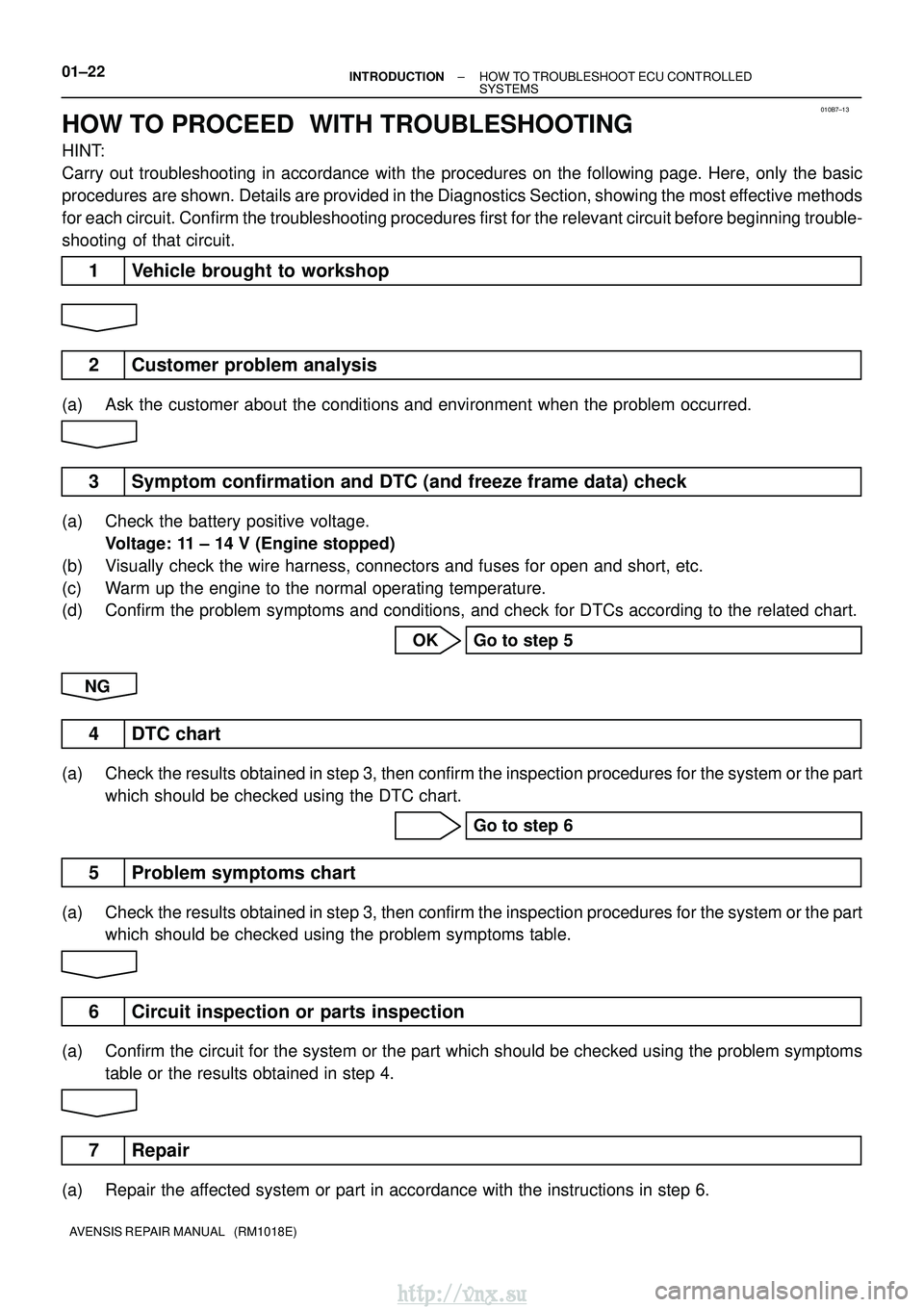
HOW TO PROCEED WITH TROUBLESHOOTING
HINT:
Carry out troubleshooting in accordance with the procedures on the follo\
wing page. Here, only the basic
procedures are shown. Details are provided in the Diagnostics Section, showing the most effective methods
for each circuit. Confirm the troubleshooting procedures first for the r\
elevant circuit before beginning trouble-
shooting of that circuit.
1 Vehicle brought to workshop
2 Customer problem analysis
(a) Ask the customer about the conditions and environment when the problem o\
ccurred.
3 Symptom confirmation and DTC (and freeze frame data) check
(a) Check the battery positive voltage. Voltage: 11 ± 14 V (Engine stopped)
(b) Visually check the wire harness, connectors and fuses for open and short,\
etc.
(c) Warm up the engine to the normal operating temperature.
(d) Confirm the problem symptoms and conditions, and check for DTCs accordin\
g to the related chart.
OK Go to step 5
NG
4 DTC chart
(a) Check the results obtained in step 3, then confirm the inspection procedures \
for the system or the part which should be checked using the DTC chart.
Go to step 6
5 Problem symptoms chart
(a) Check the results obtained in step 3, then confirm the inspection procedures \
for the system or the partwhich should be checked using the problem symptoms table.
6 Circuit inspection or parts inspection
(a) Confirm the circuit for the system or the part which should be checked u\
sing the problem symptoms
table or the results obtained in step 4.
7 Repair
(a) Repair the affected system or part in accordance with the instructions in step 6.
http://vnx.su
Page 1857 of 2234
AVENSIS (EWD526E)9
B
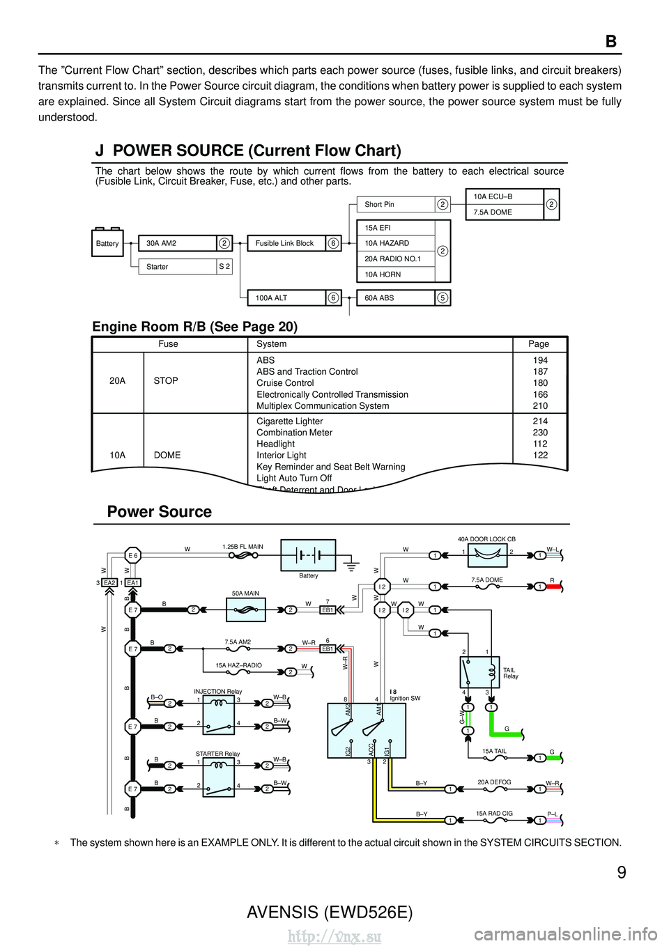
The
”Current Flow Chart” section, describes which parts each power source (fuses, fusible links\
, and circuit breakers)
transmits current to. In the Power Source circuit diagram, the condition\
s when battery power is supplied to each system
are explained. Since all System Circuit diagrams start from the power so\
urce, the power source system must be fully
understood.
ACC
S 2 6
6
5 2
22
Battery 30A AM2
Starter Short Pin
100A ALT
Fusible Link Block
60A ABS10A ECU–B
7.5A DOME
15A EFI
10A HAZARD
20A RADIO NO.1
10A HORN
20A
10A Fuse
Page
214
230
11 2
122 194
187
180
166
210
ABS
Cigarette Lighter
Combination Meter
Key Reminder and Seat Belt Warning
Light Auto Turn Off
Theft Deterrent and Door Lock ControlABS and Traction Control
Cruise Control
Electronically Controlled Transmission
Multiplex Communication System
STOP System
DOME Headlight
Interior Light
3 EA2 1 EA1E 6
E 7
E 7
2
2
2
2 2
2 2
2
INJECTION Relay
STARTER Relay
B
B
B
B–O
1
1 2
23
4
3
4
W–B W–B
B–W
B–W
E 7
E 7 B
B W
1.25B FL MAIN
50A MAIN
7.5A AM2
15A HAZ–RADIO
2
2 2
2
2W
W EB1
EB1
7
6
W–R I 2 I 2 I 2
WW
W
W W
1 1
1 140A DOOR LOCK CB
7.5A DOME
1
W–L
R
1
1
2
43 1
11
1
1 1 1
G
G
W–R
15A TAIL
20A DEFOG
B–Y
84
32Ignition SW I 8
B–Y 1 1P–L
Battery
15A RAD CIG2
TAIL
Relay
Power Source
J POWER SOURCE (Current Flow Chart)
Engine Room R/B (See Page 20)
2
W W
B
B
B
B
B
W–RWW
W
G–W AM2
AM1
IG2
IG1 W
W
The chart below shows the route by which current flows from the battery \
to each electrical source
(Fusible Link, Circuit Breaker, Fuse, etc.) and other parts.
∗ The system shown here is an EXAMPLE ONLY. It is different to the actual circuit shown in the SYSTEM CIRCUITS SECTION.
http://vnx.su
Page 2111 of 2234
544AVENSIS (EWD526E)
J POWER SOURCE (Current Flow Chart)
4
Code or Location
Parts
Electrical Source
7.5A DRL Starter S1
Location
Example
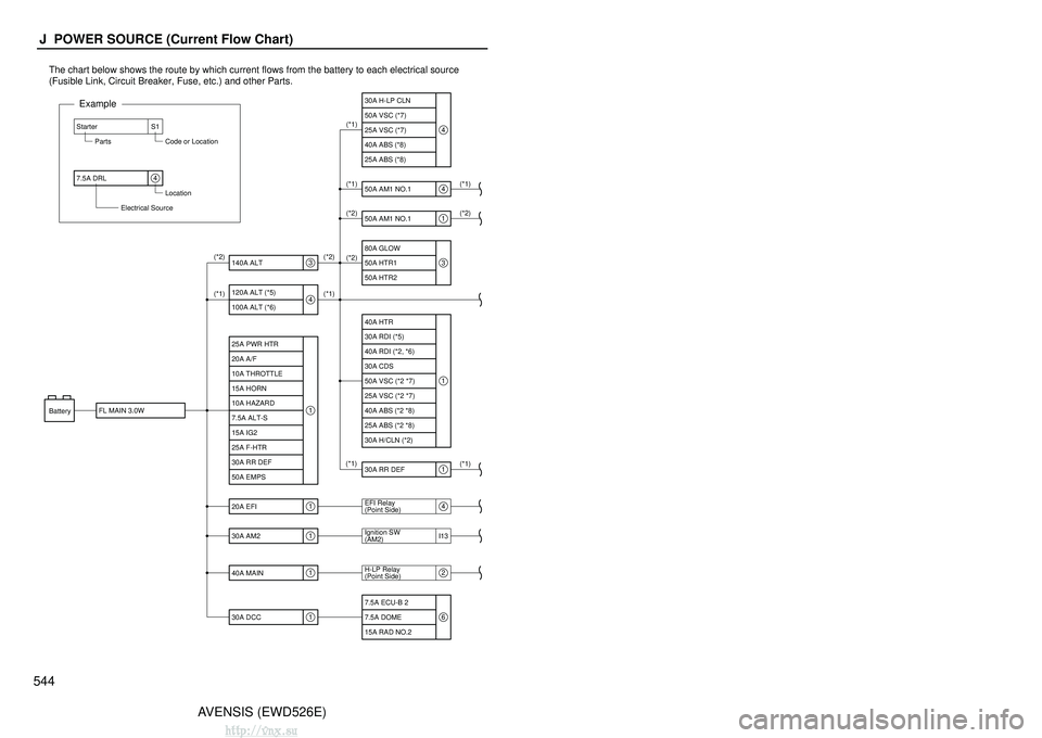
The chart below shows the route by which current flows from the battery \
to each electrical source
(Fusible Link, Circuit Breaker, Fuse, etc.) and other Parts.
Battery
I13
25A PWR HTR 30A H-LP CLN
50A VSC (*7)
25A VSC (*7)
(*1)
(*1) (*1)
(*1)
(*1)(*2)
(*1) (*2)
(*2)
(*2)
(*1) (*2) 40A ABS (*8)
25A ABS (*8)
50A AM1 NO.1
50A AM1 NO.1
80A GLOW
50A HTR1
50A HTR2
40A HTR
30A RDI (*5)
40A RDI (*2, *6)
30A CDS
50A VSC (*2 *7)
25A VSC (*2 *7)
40A ABS (*2 *8)
25A ABS (*2 *8)
30A H/CLN (*2)
30A RR DEF
EFI Relay
(Point Side)
Ignition SW
(AM2)
H-LP Relay
(Point Side)
7.5A ECU-B 2
7.5A DOME
15A RAD NO.2
20A A/F
10A THROTTLE
15A HORN
10A HAZARD
7.5A ALT-S
15A IG2
25A F-HTR
30A RR DEF
50A EMPS 120A ALT (*5)
100A ALT (*6)
FL MAIN 3.0W 140A ALT
20A EFI
30A AM2
40A MAIN
30A DCC1
4
3
1
1
1
1
4
4
1
3
1
1
4
2
6
AVENSIS (EWD526E)
545J
R9
I13
30A PWR SEAT
10A FUEL OPN
7.5A ECU-B 1
20A D-FR P/W
20A D-RR P/W
20A P-FR P/W
20A P-RR P/W
20A FR DIC
FR DEICER Relay
10A MIR HTR
15A CIG
7.5A RAD NO.1
10A GAUGE1
7.5A GAUGE2
25A WIP
20A RR WIP
10A HTR
7.5A ECU-IG
30A PWR SEAT
7.5A RR FOG
20A S/ROOF
15A STOP
15A P/POINT
15A FR FOG
7.5A OBD2
25A DOOR
* 1:Gasoline
* 2:1CD-FTV
* 3:w/ Daytime Running Light
* 4:w/o Daytime Running Light
* 5:1AZ-FSE, 1AZ-FE
* 6:1ZZ-FE, 3ZZ-FE
* 7:w/ VSC
* 8:w/o VSC
Ignition SW (Point Side)
(AM1)
20A S-HTR
10A TAIL
7.5A PANEL
25A AM1
SEAT HTR Relay
IG1 Relay
TAIL Relay (Point Side)
(Point Side)
(Point Side)
Rear Window
Defogger Relay
10A EFI NO.1
DIM Relay
(Point Side) 10A H-LP HI RH 10A H-LP HI LH 15A H-LP RH 15A H-LP LH 7.5A ST
10A IGN 7.5A DEF I/UP
7.5A EFI NO.2
(*1)
(*2)
(*1)
(*3)
(*4)
(*3)
(*1)
6
6
7
7
7
7
7
7
7
7
7
4
22
2
6
6
65
7
1: Engine Room R/B No.1 (See Page 24 (*1) or 25 (*2))
2: Engine Room R/B No.2 (See Page 26)
3: Engine Room R/B No.3 (See Page 26)
4: Engine Room R/B No.4 (See Page 27)
5: Driver Side R/B (See Page 28)
6: Fuse Block (See Page 29)
7: Driver Side J/B (See Page 30)
[LOCATION]
http://vnx.su
Page 2112 of 2234
544AVENSIS (EWD526E)
J POWER SOURCE (Current Flow Chart)
4
Code or Location
Parts
Electrical Source
7.5A DRL Starter S1
Location
Example
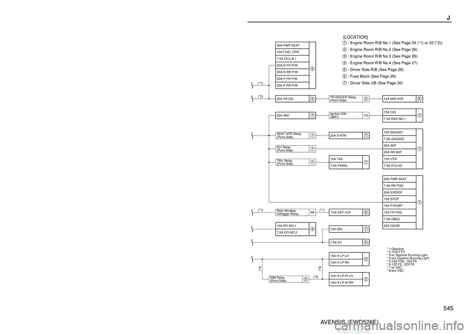
The chart below shows the route by which current flows from the battery \
to each electrical source
(Fusible Link, Circuit Breaker, Fuse, etc.) and other Parts.
Battery
I13
25A PWR HTR 30A H-LP CLN
50A VSC (*7)
25A VSC (*7)
(*1)
(*1) (*1)
(*1)
(*1)(*2)
(*1) (*2)
(*2)
(*2)
(*1) (*2) 40A ABS (*8)
25A ABS (*8)
50A AM1 NO.1
50A AM1 NO.1
80A GLOW
50A HTR1
50A HTR2
40A HTR
30A RDI (*5)
40A RDI (*2, *6)
30A CDS
50A VSC (*2 *7)
25A VSC (*2 *7)
40A ABS (*2 *8)
25A ABS (*2 *8)
30A H/CLN (*2)
30A RR DEF
EFI Relay
(Point Side)
Ignition SW
(AM2)
H-LP Relay
(Point Side)
7.5A ECU-B 2
7.5A DOME
15A RAD NO.2
20A A/F
10A THROTTLE
15A HORN
10A HAZARD
7.5A ALT-S
15A IG2
25A F-HTR
30A RR DEF
50A EMPS 120A ALT (*5)
100A ALT (*6)
FL MAIN 3.0W 140A ALT
20A EFI
30A AM2
40A MAIN
30A DCC1
4
3
1
1
1
1
4
4
1
3
1
1
4
2
6
AVENSIS (EWD526E)
545J
R9
I13
30A PWR SEAT
10A FUEL OPN
7.5A ECU-B 1
20A D-FR P/W
20A D-RR P/W
20A P-FR P/W
20A P-RR P/W
20A FR DIC
FR DEICER Relay
10A MIR HTR
15A CIG
7.5A RAD NO.1
10A GAUGE1
7.5A GAUGE2
25A WIP
20A RR WIP
10A HTR
7.5A ECU-IG
30A PWR SEAT
7.5A RR FOG
20A S/ROOF
15A STOP
15A P/POINT
15A FR FOG
7.5A OBD2
25A DOOR
* 1:Gasoline
* 2:1CD-FTV
* 3:w/ Daytime Running Light
* 4:w/o Daytime Running Light
* 5:1AZ-FSE, 1AZ-FE
* 6:1ZZ-FE, 3ZZ-FE
* 7:w/ VSC
* 8:w/o VSC
Ignition SW (Point Side)
(AM1)
20A S-HTR
10A TAIL
7.5A PANEL
25A AM1
SEAT HTR Relay
IG1 Relay
TAIL Relay (Point Side)
(Point Side)
(Point Side)
Rear Window
Defogger Relay
10A EFI NO.1
DIM Relay
(Point Side) 10A H-LP HI RH 10A H-LP HI LH 15A H-LP RH 15A H-LP LH 7.5A ST
10A IGN 7.5A DEF I/UP
7.5A EFI NO.2
(*1)
(*2)
(*1)
(*3)
(*4)
(*3)
(*1)
6
6
7
7
7
7
7
7
7
7
7
4
22
2
6
6
65
7
1: Engine Room R/B No.1 (See Page 24 (*1) or 25 (*2))
2: Engine Room R/B No.2 (See Page 26)
3: Engine Room R/B No.3 (See Page 26)
4: Engine Room R/B No.4 (See Page 27)
5: Driver Side R/B (See Page 28)
6: Fuse Block (See Page 29)
7: Driver Side J/B (See Page 30)
[LOCATION]
http://vnx.su
Page 2113 of 2234
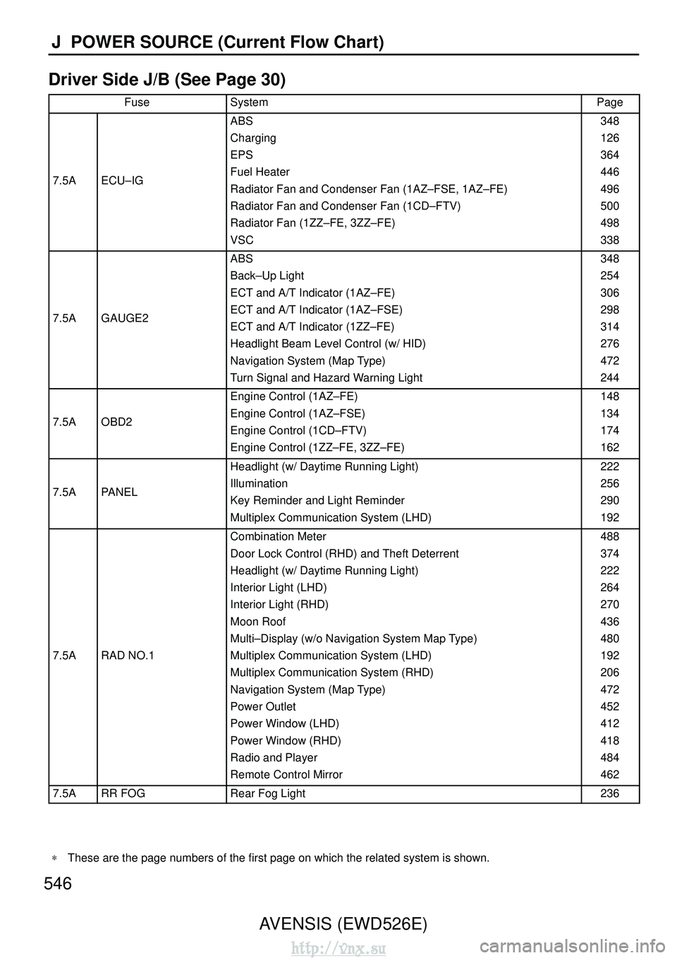
546AVENSIS (EWD526E)
J POWER SOURCE (Current Flow Chart)
Driver Side J/B (See Page 30)
FuseSystemPage
7.5AECU–IG
ABS
Charging
EPS
Fuel Heater
Radiator Fan and Condenser Fan (1AZ–FSE, 1AZ–FE)
Radiator Fan and Condenser Fan (1CD–FTV)
Radiator Fan (1ZZ–FE, 3ZZ–FE)
VSC348
126
364
446
496
500
498
338
7.5AGAUGE2
ABS
Back–Up Light
ECT and A/T Indicator (1AZ–FE)
ECT and A/T Indicator (1AZ–FSE)
ECT and A/T Indicator (1ZZ–FE)
Headlight Beam Level Control (w/ HID)
Navigation System (Map Type)
Turn Signal and Hazard Warning Light348
254
306
298
314
276
472
244
7.5AOBD2
Engine Control (1AZ–FE)
Engine Control (1AZ–FSE)
Engine Control (1CD–FTV)
Engine Control (1ZZ–FE, 3ZZ–FE)148
134
174
162
7.5APANEL
Headlight (w/ Daytime Running Light)
Illumination
Key Reminder and Light Reminder
Multiplex Communication System (LHD)222
256
290
192
7.5ARAD NO.1
Combination Meter
Door Lock Control (RHD) and Theft Deterrent
Headlight (w/ Daytime Running Light)
Interior Light (LHD)
Interior Light (RHD)
Moon Roof
Multi–Display (w/o Navigation System Map Type)
Multiplex Communication System (LHD)
Multiplex Communication System (RHD)
Navigation System (Map Type)
Power Outlet
Power Window (LHD)
Power Window (RHD)
Radio and Player
Remote Control Mirror488
374
222
264
270
436
480
192
206
472
452
412
418
484
462
7.5ARR FOGRear Fog Light236
∗
These are the page numbers of the first page on which the related system\
is shown.
http://vnx.su
Page 2115 of 2234
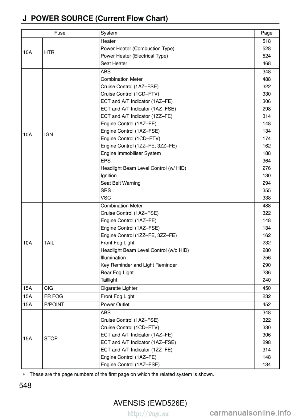
548AVENSIS (EWD526E)
J POWER SOURCE (Current Flow Chart)
FuseSystemPage
10AHTR
Heater
Power Heater (Combustion Type)
Power Heater (Electrical Type)
Seat Heater518
528
524
468
10AIGN
ABS
Combination Meter
Cruise Control (1AZ–FSE)
Cruise Control (1CD–FTV)
ECT and A/T Indicator (1AZ–FE)
ECT and A/T Indicator (1AZ–FSE)
ECT and A/T Indicator (1ZZ–FE)
Engine Control (1AZ–FE)
Engine Control (1AZ–FSE)
Engine Control (1CD–FTV)
Engine Control (1ZZ–FE, 3ZZ–FE)
Engine Immobiliser System
EPS
Headlight Beam Level Control (w/ HID)
Ignition
Seat Belt Warning
SRS
VSC348
488
322
330
306
298
314
148
134
174
162
188
364
276
130
294
355
338
10ATAIL
Combination Meter
Cruise Control (1AZ–FSE)
Engine Control (1AZ–FE)
Engine Control (1AZ–FSE)
Engine Control (1ZZ–FE, 3ZZ–FE)
Front Fog Light
Headlight Beam Level Control (w/o HID)
Illumination
Key Reminder and Light Reminder
Rear Fog Light
Taillight488
322
148
134
162
232
280
256
290
236
240
15ACIGCigarette Lighter450
15AFR FOGFront Fog Light232
15AP/POINTPower Outlet452
15ASTOP
ABS
Cruise Control (1AZ–FSE)
Cruise Control (1CD–FTV)
ECT and A/T Indicator (1AZ–FE)
ECT and A/T Indicator (1AZ–FSE)
ECT and A/T Indicator (1ZZ–FE)
Engine Control (1AZ–FE)
Engine Control (1AZ–FSE)348
322
330
306
298
314
148
134
∗
These are the page numbers of the first page on which the related system\
is shown.
http://vnx.su
Page 2117 of 2234
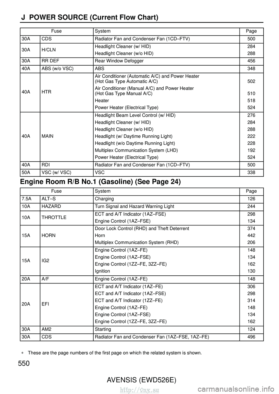
550AVENSIS (EWD526E)
J POWER SOURCE (Current Flow Chart)
FuseSystemPage
30ACDSRadiator Fan and Condenser Fan (1CD–FTV)500
30AH/CLNHeadlight Cleaner (w/ HID)
Headlight Cleaner (w/o HID)284
288
30ARR DEFRear Window Defogger456
40AABS (w/o VSC)ABS348
40AHTR
Air Conditioner (Automatic A/C) and Power Heater
(Hot Gas Type Automatic A/C)
Air Conditioner (Manual A/C) and Power Heater
(Hot Gas Type Manual A/C)
Heater
Power Heater (Electrical Type)
502
510
518
524
40AMAIN
Headlight Beam Level Control (w/ HID)
Headlight Cleaner (w/ HID)
Headlight Cleaner (w/o HID)
Headlight (w/ Daytime Running Light)
Headlight (w/o Daytime Running Light)
Multiplex Communication System (LHD)
Power Heater (Electrical Type)276
284
288
222
228
192
524
40ARDIRadiator Fan and Condenser Fan (1CD–FTV)500
50AVSC (w/ VSC)VSC338
Engine Room R/B No.1 (Gasoline) (See Page 24)
FuseSystemPage
7.5AALT–SCharging126
10AHAZARDTurn Signal and Hazard Warning Light244
10ATHROTTLEECT and A/T Indicator (1AZ–FSE)
Engine Control (1AZ–FSE)298
134
15AHORN
Door Lock Control (RHD) and Theft Deterrent
Horn
Multiplex Communication System (RHD)374
442
206
15AIG2
Engine Control (1AZ–FE)
Engine Control (1AZ–FSE)
Engine Control (1ZZ–FE, 3ZZ–FE)
Ignition148
134
162
130
20AA/FEngine Control (1AZ–FE)148
20AEFI
ECT and A/T Indicator (1AZ–FE)
ECT and A/T Indicator (1AZ–FSE)
ECT and A/T Indicator (1ZZ–FE)
Engine Control (1AZ–FE)
Engine Control (1AZ–FSE)
Engine Control (1ZZ–FE, 3ZZ–FE)306
298
314
148
134
162
30AAM2Starting124
30ACDSRadiator Fan and Condenser Fan (1AZ–FSE, 1AZ–FE)496
∗
These are the page numbers of the first page on which the related system\
is shown.
http://vnx.su
Page 2119 of 2234
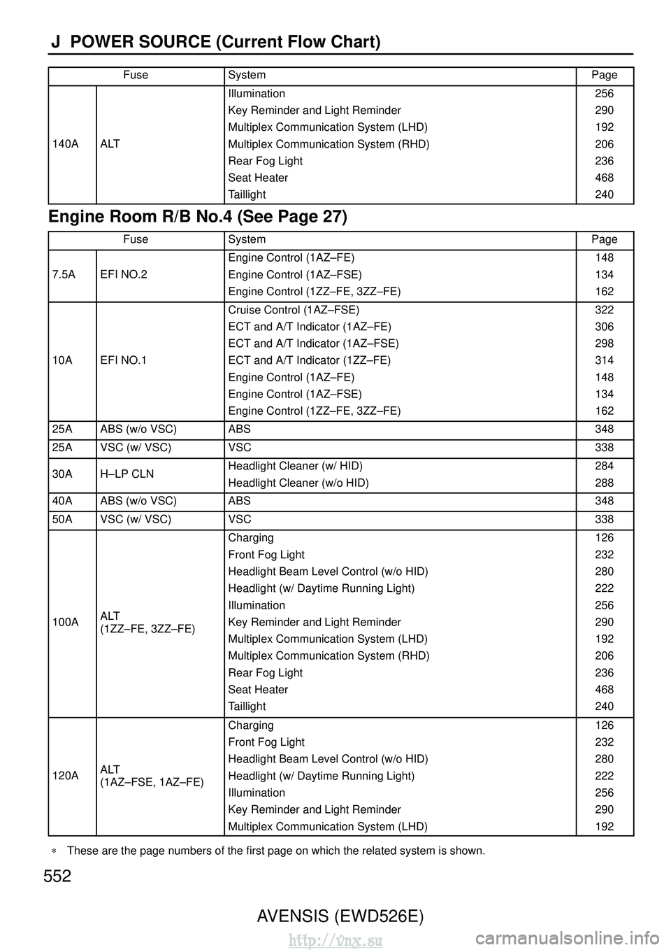
552AVENSIS (EWD526E)
J POWER SOURCE (Current Flow Chart)
FuseSystemPage
140AALT
Illumination
Key Reminder and Light Reminder
Multiplex Communication System (LHD)
Multiplex Communication System (RHD)
Rear Fog Light
Seat Heater
Taillight256
290
192
206
236
468
240
Engine Room R/B No.4 (See Page 27)
FuseSystemPage
7.5AEFI NO.2
Engine Control (1AZ–FE)
Engine Control (1AZ–FSE)
Engine Control (1ZZ–FE, 3ZZ–FE)148
134
162
10AEFI NO.1
Cruise Control (1AZ–FSE)
ECT and A/T Indicator (1AZ–FE)
ECT and A/T Indicator (1AZ–FSE)
ECT and A/T Indicator (1ZZ–FE)
Engine Control (1AZ–FE)
Engine Control (1AZ–FSE)
Engine Control (1ZZ–FE, 3ZZ–FE)322
306
298
314
148
134
162
25AABS (w/o VSC)ABS348
25AVSC (w/ VSC)VSC338
30AH–LP CLNHeadlight Cleaner (w/ HID)
Headlight Cleaner (w/o HID)284
288
40AABS (w/o VSC)ABS348
50AVSC (w/ VSC)VSC338
100AALT
(1ZZ–FE, 3ZZ–FE)
Charging
Front Fog Light
Headlight Beam Level Control (w/o HID)
Headlight (w/ Daytime Running Light)
Illumination
Key Reminder and Light Reminder
Multiplex Communication System (LHD)
Multiplex Communication System (RHD)
Rear Fog Light
Seat Heater
Taillight126
232
280
222
256
290
192
206
236
468
240
120AALT
(1AZ–FSE, 1AZ–FE)
Charging
Front Fog Light
Headlight Beam Level Control (w/o HID)
Headlight (w/ Daytime Running Light)
Illumination
Key Reminder and Light Reminder
Multiplex Communication System (LHD)126
232
280
222
256
290
192
∗
These are the page numbers of the first page on which the related system\
is shown.
http://vnx.su