Page 768 of 2234

A62787
1.0 ± 1.4 mm30
�
45
�
A62788
1.0 ± 1.4 mm 60
�
45 �
P16860
A01080
14±32
±
ENGINE MECHANICAL CYLINDER HEAD ASSY (1ZZ±FE/3ZZ±FE)
1ZZ±FE,3ZZ±FE ENGINE REPAIR MANUAL
(RM923E)
(2) If blue appears 360� around the valve seat, the
guide and face are concentric. If not, resurface the
seat.
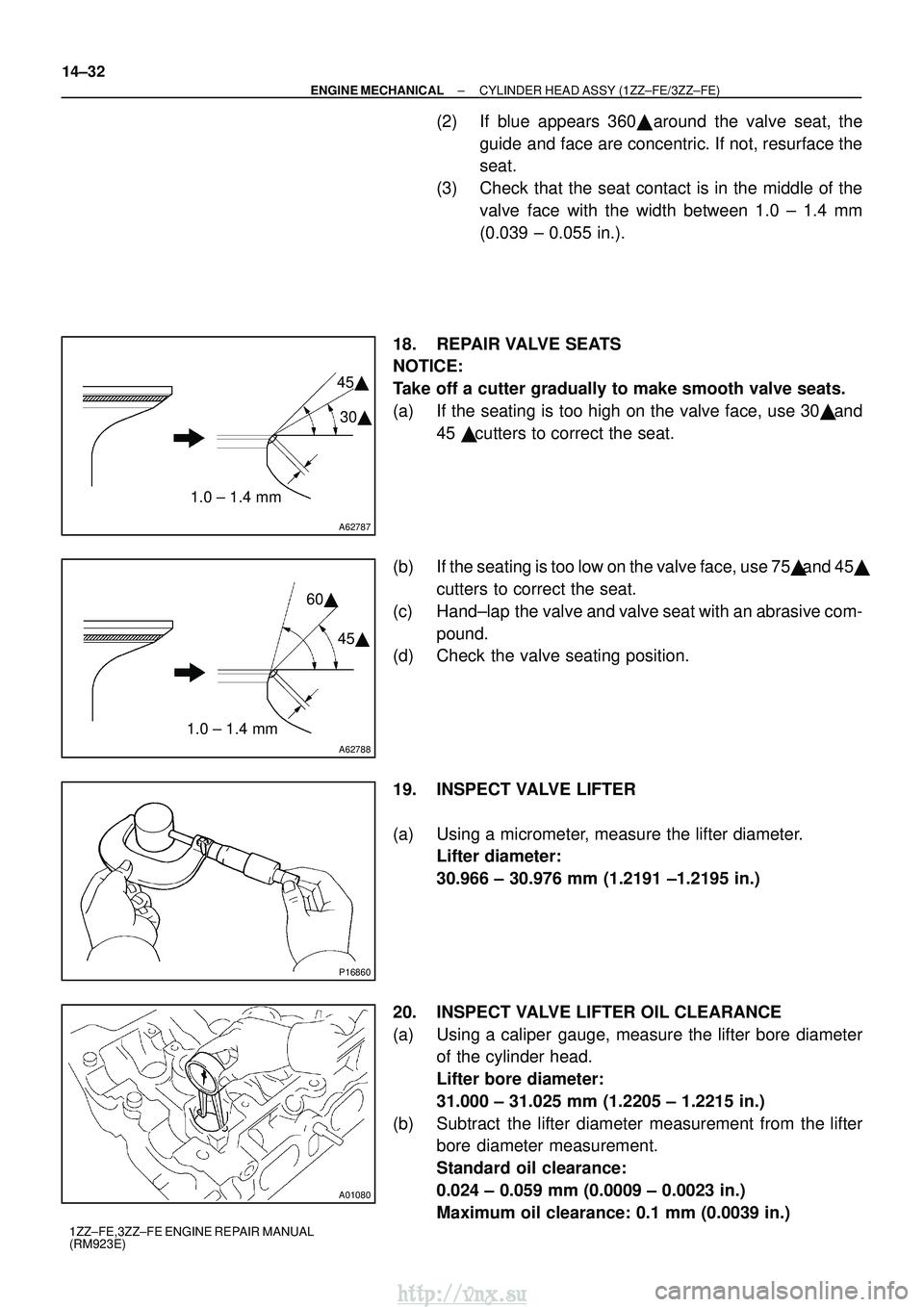
(3) Check that the seat contact is in the middle of the valve face with the width between 1.0 ± 1.4 mm
(0.039 ± 0.055 in.).
18. REPAIR VALVE SEATS
NOTICE:
Take off a cutter gradually to make smooth valve seats.
(a) If the seating is too high on the valve face, use 30 � and
45 � cutters to correct the seat.
(b) If the seating is too low on the valve face, use 75 � and 45�
cutters to correct the seat.
(c) Hand±lap the valve and valve seat with an abrasive com- pound.
(d) Check the valve seating position.
19. INSPECT VALVE LIFTER
(a) Using a micrometer, measure the lifter diameter. Lifter diameter:
30.966 ± 30.976 mm (1.2191 ±1.2195 in.)
20. INSPECT VALVE LIFTER OIL CLEARANCE
(a) Using a caliper gauge, measure the lifter bore diameter of the cylinder head.
Lifter bore diameter:
31.000 ± 31.025 mm (1.2205 ± 1.2215 in.)
(b) Subtract the lifter diameter measurement from the lifter bore diameter measurement.
Standard oil clearance:
0.024 ± 0.059 mm (0.0009 ± 0.0023 in.)
Maximum oil clearance: 0.1 mm (0.0039 in.)
http://vnx.su
Page 1009 of 2234

2600L±02
F44617
Front:AB
F44618
Rear:
C D
SA3213
A
D B
Front
C
F44619
26±6
±
FRONT SUSPENSION FRONT WHEEL ALIGNMENT
AVENSIS REPAIR MANUAL (RM1018E)
FRONT WHEEL ALIGNMENT
ADJUSTMENT
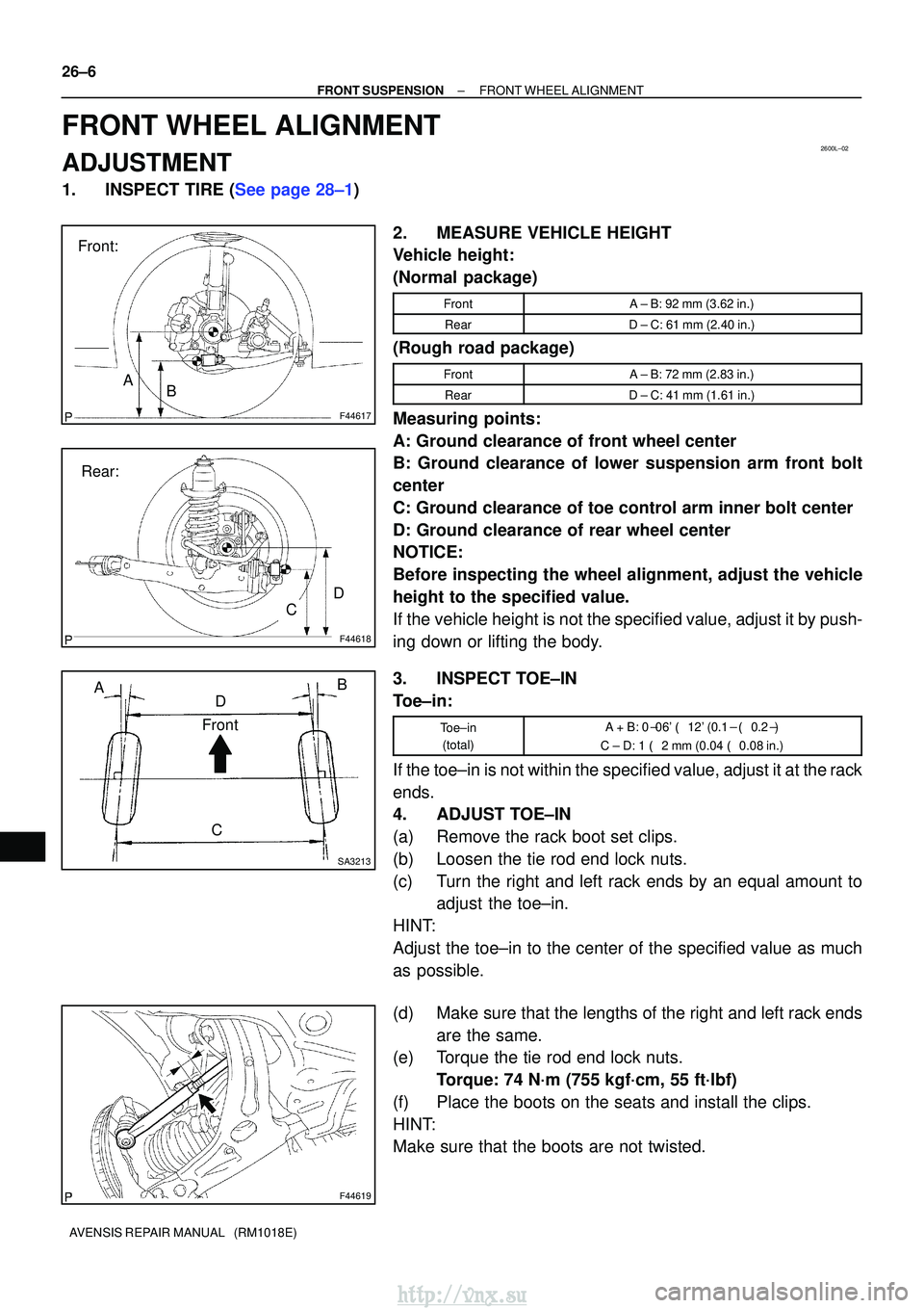
1.INSPECT TIRE (See page 28±1) 2. MEASURE VEHICLE HEIGHT
Vehicle height:
(Normal package)
FrontA ± B: 92 mm (3.62 in.)
RearD ± C: 61 mm (2.40 in.)
(Rough road package)
FrontA ± B: 72 mm (2.83 in.)
RearD ± C: 41 mm (1.61 in.)
Measuring points:
A: Ground clearance of front wheel center
B: Ground clearance of lower suspension arm front bolt
center
C: Ground clearance of toe control arm inner bolt center
D: Ground clearance of rear wheel center
NOTICE:
Before inspecting the wheel alignment, adjust the vehicle
height to the specified value.
If the vehicle height is not the specified value, adjust it by push-
ing down or lifting the body.
3. INSPECT TOE±IN
Toe±in:
Toe±in(total)A + B: 0� 06' � 12' (0.1 � � 0.2� )
C ± D: 1 � 2 mm (0.04 � 0.08 in.)
If the toe±in is not within the specified value, adjust it at the rack
ends.
4. ADJUST TOE±IN
(a) Remove the rack boot set clips.
(b) Loosen the tie rod end lock nuts.
(c) Turn the right and left rack ends by an equal amount to
adjust the toe±in.
HINT:
Adjust the toe±in to the center of the specified value as much
as possible.
(d) Make sure that the lengths of the right and left rack ends are the same.
(e) Torque the tie rod end lock nuts.
Torque: 74 N´m (755 kgf´cm, 55 ft´lbf)
(f) Place the boots on the seats and install the clips.
HINT:
Make sure that the boots are not twisted.
http://vnx.su
Page 1700 of 2234
720JG±01
72±36
±
SEATSEAT HEATER SYSTEM
AVENSIS REPAIR MANUAL (RM1018E)
PROBLEM SYMPTOMS TABLE
SymptomSuspected AreaSee Page
Seat heaters do not operate
(Seat is not warmed up)
1. SEAT HTR relay
2. S±HTR fuse
3. Seat heater switch
4. Seat heater control sub±assy LH
5. Seat heater control sub±assy RH
6. Front seat cushion heater assy LH
7. Front seat cushion heater assy RH
8. Front seatback heater assy LH
9. Front seatback heater assy RH
10.Wire harness72±34
72±37
72±34
72±34
72±37
72±34
72±34
72±34
72±37
72±34
72±37
72±34
72±37
72±34
72±37 �
Temperature of seat heater cannot be adjusted
1. Seat heater switch
2. Seat heater control sub±assy LH
3. Seat heater control sub±assy RH
4. Wire harness72±34
72±37
72±34
72±34�
http://vnx.su