Page 215 of 2234
030G6±04
±
SERVICE SPECIFICATIONS POWER STEERING
03±59
AVENSIS REPAIR MANUAL (RM1018E)
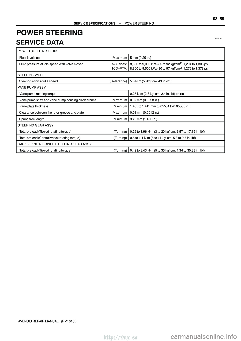
POWER STEERING
SERVICE DATA
POWER STEERING FLUID
Fluid level rise Maximum5 mm (0.20 in.)
Fluid pressure at idle speed with valve closedAZ Series:
1CD±FTV:8,300 to 9,000 kPa (85 to 92 kgf/cm2, 1,204 to 1,305 psi)
8,800 to 9,500 kPa (90 to 97 kgf/cm2, 1,276 to 1,378 psi)
STEERING WHEEL
Steering effort at idle speed (Reference)5.5 N´m (56 kgf´cm, 49 in.´lbf)
VANE PUMP ASSY
Vane pump rotating torque0.27 N´m (2.8 kgf´cm, 2.4 in.´lbf) or less
Vane pump shaft and vane pump housing oil clearance Maximum0.07 mm (0.0028 in.)
Vane plate thickness Minimum1.405 to 1.411 mm (0.05531 to 0.05555 in.)
Clearance between the rotor groove and plateMaximum0.03 mm (0.0012 in.)
Spring free length Minimum36.9 mm (1.453 in.)
STEERING GEAR ASSY
Total preload (Tie rod rotating torque) (Turning)0.29 to 1.96 N´m (3 to 20 kgf´cm, 2.57 to 17.35 in.´lbf)
Total preload (Control valve rotating torque)(Turning)0.6 to 1.1 N´m (6 to 11 kgf´cm, 5.3 to 9.7 in.´lbf)
RACK & PINION POWER STEERING GEAR ASSY
Total preload (Tie rod rotating torque) (Turning)0.49 to 3.43 N´m (5 to 35 kgf´cm, 4.34 to 30.38 in.´lbf)
http://vnx.su
Page 646 of 2234
14±134
±
ENGINE MECHANICALPARTIAL ENGINE ASSY(1AZ±FE)
AVENSIS REPAIR MANUAL (RM1018E)
155.INSTALL RADIATOR ASSY (See page 16±24)
156.INSTALL RADIATOR RELAY BLOCK Torque: 5.0 N �m (51 kgf�cm,44 in. �lbf)
157.INSTALL ENGINE COVER SUB±ASSY NO.1 Torque: 7.0 N �m (71 kgf�cm,62 in. �lbf)
158.ADD MANUAL TRANSAXLE OIL (M/T TRANSAXLE)
159.ADD AUTOMATIC TRANSAXLE FLUID (A/T TRANSAXLE)
160.ADD ENGINE OIL
161.ADD COOLANT (See page 16±19)
162. ADD POWER STEERING FLUID
163. BLEED POWER STEERING FLUID
164. CHECK FOR ENGINE OIL LEAKS
165.CHECK FOR ENGINE COOLANT LEAKS (See page 16±13)
166.CHECK FOR FUEL LEAKS (See page 11±15)
167. INSTALL FRONT WHEELS Torque: 103 N� m (1,050 kgf�cm, 76 ft �lbf)
168.ADJUST FRONT WHEEL ALIGNMENT (See page 26±6)
169.INSPECT CHECK IDLE SPEED AND IGNITION TIMING (See page 14±101)
170.INSPECT CO/HC (See page 14±101)
171. CHECK ABS SPEED SENSOR SIGNAL
http://vnx.su
Page 1172 of 2234
D30080
41±30
±
MANUAL TRANSMISSION/TRANSAXLE MANUAL TRANSAXLE ASSY (1AZ±FE/1AZ±FSE)
AVENSIS REPAIR MANUAL (RM1018E)
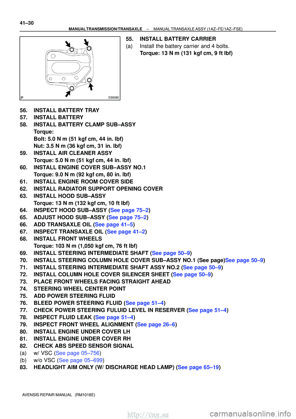
55. INSTALL BATTERY CARRIER
(a) Install the battery carrier and 4 bolts. Torque: 13 N �m (131 kgf� cm, 9 ft�lbf)
56. INSTALL BATTERY TRAY
57. INSTALL BATTERY
58. INSTALL BATTERY CLAMP SUB±ASSY Torque:
Bolt: 5.0 N �m (51 kgf �cm, 44 in. �lbf)
Nut: 3.5 N� m (36 kgf�cm, 31 in. �lbf)
59. INSTALL AIR CLEANER ASSY Torque: 5.0 N �m (51 kgf �cm, 44 in. �lbf)
60. INSTALL ENGINE COVER SUB±ASSY NO.1 Torque: 9.0 N �m (92 kgf �cm, 80 in. �lbf)
61. INSTALL ENGINE ROOM COVER SIDE
62. INSTALL RADIATOR SUPPORT OPENING COVER
63. INSTALL HOOD SUB±ASSY Torque: 13 N �m (132 kgf� cm, 10 ft�lbf)
64.INSPECT HOOD SUB±ASSY (See page 75±2)
65.ADJUST HOOD SUB±ASSY (See page 75±2)
66.ADD TRANSAXLE OIL (See page 41±5)
67.INSPECT TRANSAXLE OIL (See page 41±2)
68. INSTALL FRONT WHEELS
Torque: 103 N� m (1,050 kgf�cm, 76 ft �lbf)
69.INSTALL STEERING INTERMEDIATE SHAFT (See page 50±9)
70.INSTALL STEERING COLUMN HOLE COVER SUB±ASSY NO.1 (See page)See page 50±9)
71.INSTALL STEERING INTERMEDIATE SHAFT ASSY NO.2 (See page 50±9)
72.INSTALL COLUMN HOLE COVER SILENCER SHEET (See page 50±9)
73. PLACE FRONT WHEELS FACING STRAIGHT AHEAD
74. STEERING WHEEL CENTER POINT
75. ADD POWER STEERING FLUID
76.BLEED POWER STEERING FLUID (See page 51±4)
77.CHECK POWER STEERING FULUID LEVEL IN RESERVER (See page 51±4)
78.INSPECT FLUID LEAK (See page 51±4)
79.INSPECT FRONT WHEEL ALIGNMENT (See page 26±6)
80. INSTALL ENGINE UNDER COVER LH
81. INSTALL ENGINE UNDER COVER RH
82. CHECK ABS SPEED SENSOR SIGNAL
(a)w/ VSC (See page 05±756)
(b)w/o VSC (See page 05±699)
83.HEADLIGHT AIM ONLY (W/ DISCHARGE HEAD LAMP) (See page 65±19)
http://vnx.su
Page 1182 of 2234
41±40
±
MANUAL TRANSMISSION/TRANSAXLE MANUAL TRANSAXLE ASSY (1CD±FTV)
AVENSIS REPAIR MANUAL (RM1018E)
75. INSTALL HOOD SUB±ASSY Torque: 13 N �m (133 kgf� cm, 10 ft�lbf)
76.INSPECT HOOD SUB±ASSY (See page 75±2)
77.ADJUST HOOD SUB±ASSY (See page 75±2)
78.ADD TRANSAXLE OIL (See page 41±5)
79.INSPECT TRANSAXLE OIL (See page 41±2)
80. ADD POWER STEERING FLUID
81.BLEED POWER STEERING FLUID (See page 51±4)
82.CHECK POWER STEERING FULUID LEVEL IN RESERVER (See page 51±4)
83.INSPECT FLUID LEAK (See page 51±4)
84. INSTALL FRONT WHEELS Torque: 103 N� m (1,050 kgf�cm, 76 ft �lbf)
85.INSPECT FRONT WHEEL ALIGNMENT (See page 26±6)
86. INSTALL ENGINE UNDER COVER RH
87. INSTALL ENGINE UNDER COVER LH
88. CHECK ABS SPEED SENSOR SIGNAL
(a)w/ VSC (See page 05±756)
(b)w/o VSC (See page 05±699)
89.HEADLIGHT AIM ONLY (W/ DISCHARGE HEAD LAMP) (See page 65±19)
http://vnx.su
Page 1238 of 2234
5000D±14
50±2
±
STEERING COLUMN STEERING SYSTEM
AVENSIS REPAIR MANUAL (RM1018E)
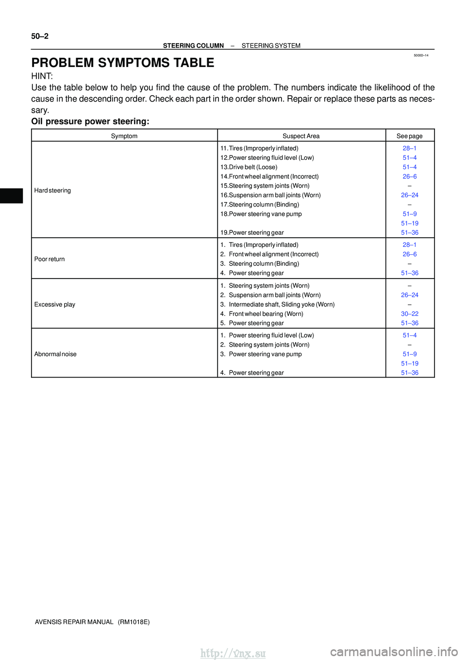
PROBLEM SYMPTOMS TABLE
HINT:
Use the table below to help you find the cause of the problem. The numbers \
indicate the likelihood of the
cause in the descending order. Check each part in the order shown. Repair or replace these parts as n\
eces-
sary.
Oil pressure power steering:
SymptomSuspect AreaSee page
Hard steering
11. Tires (Improperly inflated)
12.Power steering fluid level (Low)
13.Drive belt (Loose)
14.Front wheel alignment (Incorrect)
15.Steering system joints (Worn)
16.Suspension arm ball joints (Worn)
17.Steering column (Binding)
18.Power steering vane pump
19.Power steering gear28±1
51±4
51±4
26±6 ±
26±24 ±
51±9
51±19
51±36
Poor return
1. Tires (Improperly inflated)
2. Front wheel alignment (Incorrect)
3. Steering column (Binding)
4. Power steering gear28±1
26±6 ±
51±36
Excessive play
1. Steering system joints (Worn)
2. Suspension arm ball joints (Worn)
3. Intermediate shaft, Sliding yoke (Worn)
4. Front wheel bearing (Worn)
5. Power steering gear±
26±24 ±
30±22
51±36
Abnormal noise
1. Power steering fluid level (Low)
2. Steering system joints (Worn)
3. Power steering vane pump
4. Power steering gear51±4 ±
51±9
51±19
51±36
http://vnx.su
Page 1242 of 2234
5100G±06
51±2
±
POWER STEERING POWER STEERING SYSTEM
AVENSIS REPAIR MANUAL (RM1018E)
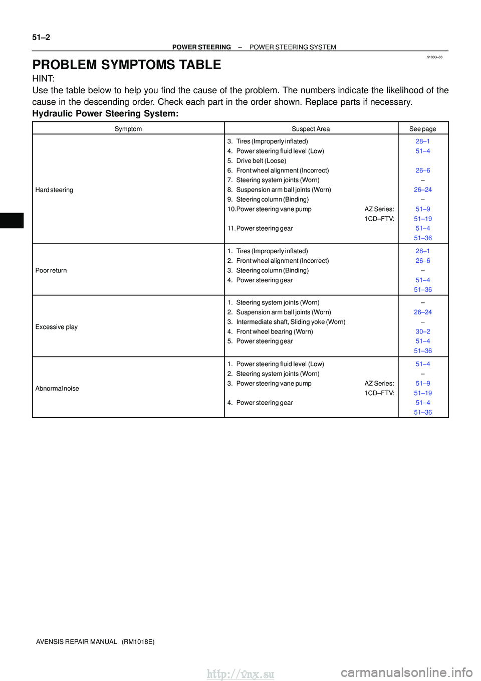
PROBLEM SYMPTOMS TABLE
HINT:
Use the table below to help you find the cause of the problem. The numbers \
indicate the likelihood of the
cause in the descending order. Check each part in the order shown. Replace parts if necessary.
Hydraulic Power Steering System:
SymptomSuspect AreaSee page
Hard steering
3. Tires (Improperly inflated)
4. Power steering fluid level (Low)
5. Drive belt (Loose)
6. Front wheel alignment (Incorrect)
7. Steering system joints (Worn)
8. Suspension arm ball joints (Worn)
9. Steering column (Binding)
10.Power steering vane pump AZ Series: 1CD±FTV:
11. Power steering gear28±1
51±4
26±6 ±
26±24 ±
51±9
51±19 51±4
51±36
Poor return
1. Tires (Improperly inflated)
2. Front wheel alignment (Incorrect)
3. Steering column (Binding)
4. Power steering gear28±1
26±6 ±
51±4
51±36
Excessive play
1. Steering system joints (Worn)
2. Suspension arm ball joints (Worn)
3. Intermediate shaft, Sliding yoke (Worn)
4. Front wheel bearing (Worn)
5. Power steering gear±
26±24 ±
30±2
51±4
51±36
Abnormal noise
1. Power steering fluid level (Low)
2. Steering system joints (Worn)
3. Power steering vane pump AZ Series: 1CD±FTV:
4. Power steering gear51±4
±
51±9
51±19 51±4
51±36
http://vnx.su
Page 1244 of 2234
510DE±02
F40449
R11229
NormalAbnormal
R00427
51±4
±
POWER STEERING POWER STEERING SYSTEM
AVENSIS REPAIR MANUAL (RM1018E)
ON±VEHICLE INSPECTION
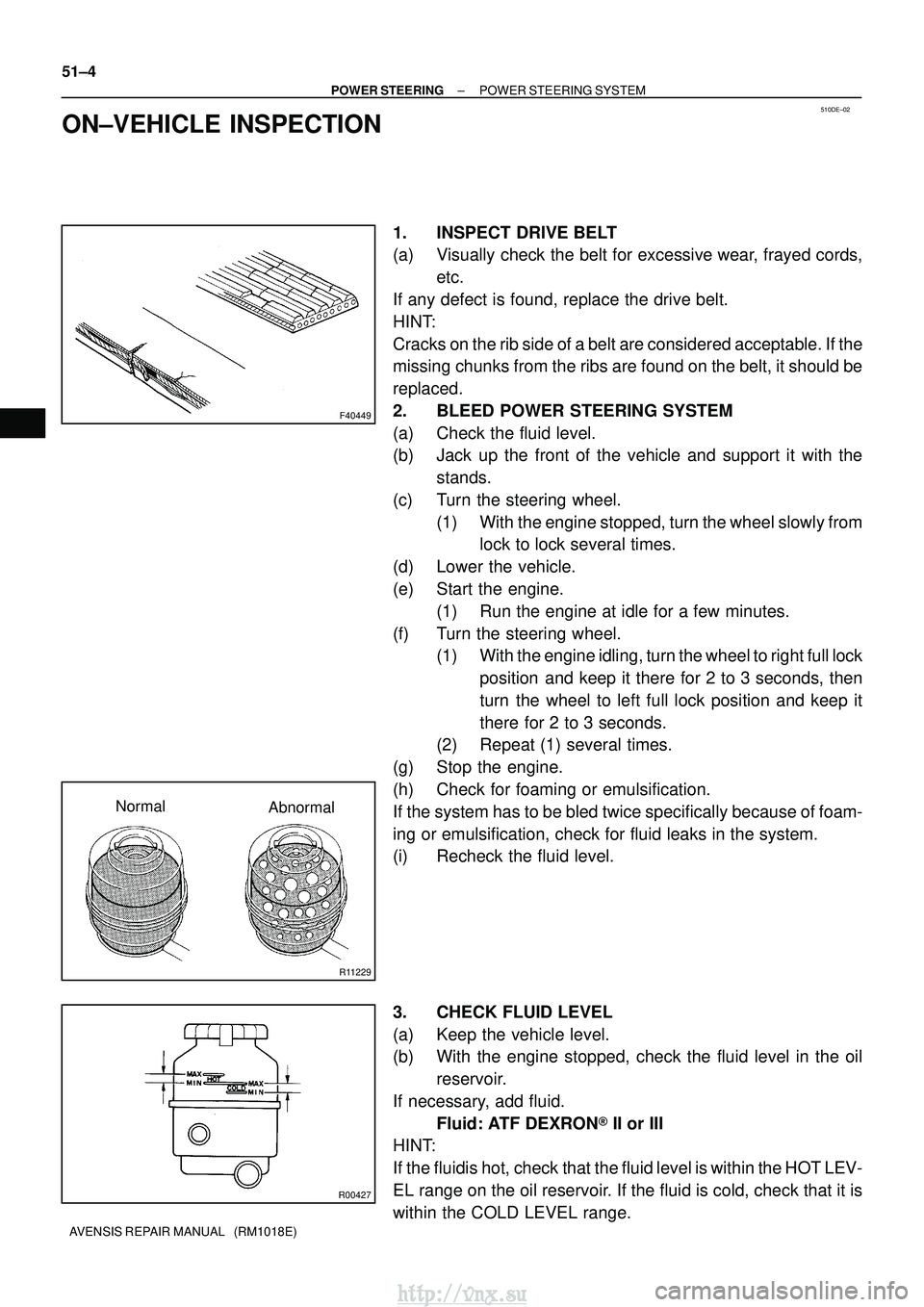
1. INSPECT DRIVE BELT
(a) Visually check the belt for excessive wear, frayed cords, etc.
If any defect is found, replace the drive belt.
HINT:
Cracks on the rib side of a belt are considered acceptable. If the
missing chunks from the ribs are found on the belt, it should be
replaced.
2. BLEED POWER STEERING SYSTEM
(a) Check the fluid level.
(b) Jack up the front of the vehicle and support it with the stands.
(c) Turn the steering wheel. (1) With the engine stopped, turn the wheel slowly fromlock to lock several times.
(d) Lower the vehicle.
(e) Start the engine. (1) Run the engine at idle for a few minutes.
(f) Turn the steering wheel. (1) With the engine idling, turn the wheel to right full lock
position and keep it there for 2 to 3 seconds, then
turn the wheel to left full lock position and keep it
there for 2 to 3 seconds.
(2) Repeat (1) several times.
(g) Stop the engine.
(h) Check for foaming or emulsification.
If the system has to be bled twice specifically because of foam-
ing or emulsification, check for fluid leaks in the system.
(i) Recheck the fluid level.
3. CHECK FLUID LEVEL
(a) Keep the vehicle level.
(b) With the engine stopped, check the fluid level in the oil reservoir.
If necessary, add fluid. Fluid: ATF DEXRON� II or III
HINT:
If the fluidis hot, check that the fluid level is within the HOT LEV-
EL range on the oil reservoir. If the fluid is cold, check that it is
within the COLD LEVEL range.
http://vnx.su
Page 1245 of 2234
R11229
NormalAbnormal
R11786Engine Idling Engine Stopped5 mm (0.20 in.)
or less
±
POWER STEERING POWER STEERING SYSTEM
51±5
AVENSIS REPAIR MANUAL (RM1018E)
(c) Start the engine and run it at idle.
(d) Turn the steering wheel from lock to lock several times to
boost fluid temperature.
Fluid temperature: 80� C (176�F)
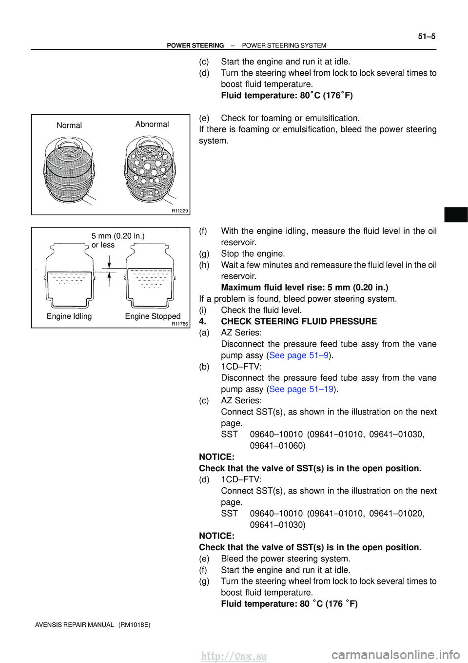
(e) Check for foaming or emulsification.
If there is foaming or emulsification, bleed the power steering
system.
(f) With the engine idling, measure the fluid level in the oil reservoir.
(g) Stop the engine.
(h) Wait a few minutes and remeasure the fluid level in the oil reservoir.
Maximum fluid level rise: 5 mm (0.20 in.)
If a problem is found, bleed power steering system.
(i) Check the fluid level.
4. CHECK STEERING FLUID PRESSURE
(a) AZ Series: Disconnect the pressure feed tube assy from the vane
pump assy (See page 51±9).
(b) 1CD±FTV: Disconnect the pressure feed tube assy from the vane
pump assy (See page 51±19).
(c) AZ Series: Connect SST(s), as shown in the illustration on the next
page.
SST 09640±10010 (09641±01010, 09641±01030, 09641±01060)
NOTICE:
Check that the valve of SST(s) is in the open position.
(d) 1CD±FTV: Connect SST(s), as shown in the illustration on the next
page.
SST 09640±10010 (09641±01010, 09641±01020, 09641±01030)
NOTICE:
Check that the valve of SST(s) is in the open position.
(e) Bleed the power steering system.
(f) Start the engine and run it at idle.
(g) Turn the steering wheel from lock to lock several times to
boost fluid temperature.
Fluid temperature: 80 �C (176 �F)
http://vnx.su