MO
NEW MODEL OUTLINE
�������
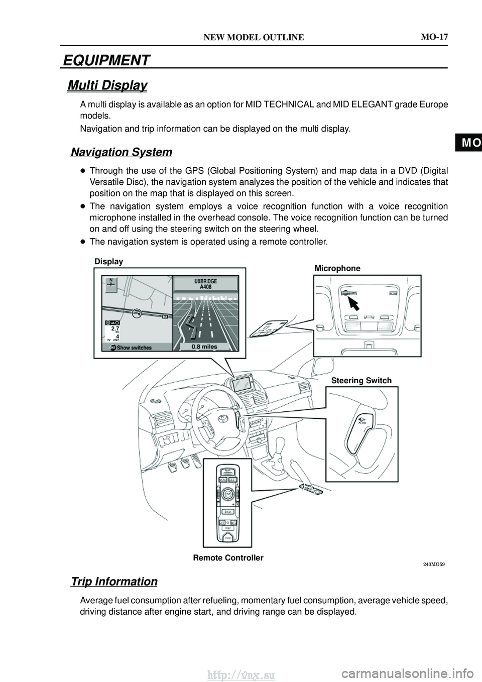
DisplayMicrophone
Steering Switch
Remote Controller
MO-17
EQUIPMENT
Multi Display
A multi display is available as an option for MID TECHNICAL and MID ELEG\
ANT grade Europe
models.
Navigation and trip information can be displayed on the multi display.
Navigation System
� Through the use of the GPS (Global Positioning System) and map data in a DVD \
(Digital
Versatile Disc), the navigation system analyzes the position of the vehi\
cle and indicates that
position on the map that is displayed on this screen.
� The navigation system employs a voice recognition function with a voice \
recognition
microphone installed in the overhead console. The voice recognition function can b\
e turned
on and off using the steering switch on the steering wheel.
� The navigation system is operated using a remote controller.
Trip Information
Average fuel consumption after refueling, momentary fuel consumption, ave\
rage vehicle speed,
driving distance after engine start, and driving range can be displayed.\
http://vnx.su
010B6±13
±
INTRODUCTIONHOW TO TROUBLESHOOT ECU CONTROLLED
SYSTEMS01±21
AVENSIS REPAIR MANUAL (RM1018E)
HOW TO TROUBLESHOOT ECU CONTROLLED SYSTEMS
GENERAL INFORMATION
There are many ECU controlled systems used in the AVENSIS. In general, ECU controlled system are con-
sidered to be very intricate and require a high level of technical knowledge an\
d expert skill to troubleshoot.
The fact is, however, that if you proceed by inspecting the circuits one by one, troubleshoo\
ting of these sys-
tems is not complex. If you have adequate understanding of the system and ba\
sic knowledge of electricity,
the problem can be accurately diagnosed and fixed. This manual is design\
ed based on the above principle
to help service technicians perform accurate and effective troubleshooting, and is compiled for the following
major ECU controlled systems:
The troubleshooting procedures are described on the following pages.
SystemPage
1. SFI System [1ZZ±FE, 3ZZ±FE]05±1
2. SFI System [1AZ±FE]05±143
3. SFI System [1AZ±FSE]05±290
4. ECD System [1CD±FTV]05±523
5. ABS with EBD System05±696
6. ABS with EBD & BA & TRC & VSC System05±752
7. Electronic Controlled Automatic Transmission [ECT] [U241 (1AZ±FE)]05±856
8. Electronic Controlled Automatic Transmission [ECT] [U241 (1AZ±FSE)]05±915
9. Electronic Controlled Automatic Transmission [ECT] [U341]05±980
10.Electronic Motor Power Steering System05±1042
11. Air Conditioning System05±1088
12.Combustion Type Power Heater System05±1161
13.Supplemental Restraint System05±1181
14.Audio System05±1393
15.Navigation System05±1435
16.Combination Meter05±1497
17.Power Door Lock Control System05±1534
18.Wireless Door Lock Control System05±1568
19.Key Reminder Warning System05±1586
20.Engine Immobiliser System05±1599
21.Theft Deterrent System05±1627
22.Multiplex Communication System05±1654
23.Cruise Control System05±1697
FOR USING HAND±HELD TESTER
�Before using the tester, the tester's operator manual should be read thoroughly.
�If the tester cannot communicate with the ECU controlled systems when you \
have connected the cable
of tester to the DLC3, turned the ignition switch ON and operated the test\
er, there is a problem on the
vehicle side or tester side.
(1) If the communication is normal when the tester is connected to another veh\
icle, inspect the diag-
nosis data link line (Bus �line) or ECU power circuit of the vehicle.
(2) If the communication is still impossible when the tester is connected to a\
nother vehicle, the prob- lem is probably in the tester itself, so perform the Self Test procedures outlined in the Tester Oper-
ator 's Manual.
http://vnx.su

HOW TO TROUBLESHOOT ECU CONTROLLED SYSTEMS
GENERAL INFORMATION
There are many ECU controlled")