Page 13 of 2234

MO
NEW MODEL OUTLINE
�������
Steering Pad SwitchSteering Pad Switch
1 3 2 4
MO-13
Steering Wheel
�
ENTRY grade models feature a urethane 4-spoke type steering wheel, and MID T\
ECHNICAL
and MID ELEGANT grade models feature a leather 4-spoke type steering whe\
el.
� Europe models feature a steering pad switch that enables drivers to oper\
ate the audio system,
switch to trip information display, and turn the navigation system's voice recognition function
on and off without removing their hands from the steering wheel.
Steering Pad Switch Function
System ButtonPress for a short period Press for a long period
Mode 1 Switch AM / FM of radio or TAPE or CD Switch to OFF
Volume 2 UP / DOWN for audio system volume
Audio Radio Channel UP / DOWN UP / DOWN to select a station
Seek Tape 3
Search FF / REW FF / REW
CD Track UP / DOWN Disc UP / DOWN
Trip Information 4 Switching trip information display In the case of average vehicle speed mode
or driving distance after engine start mode,
reset each information
Navigation 4Voice recognition ON / OFF Ð
http://vnx.su
Page 20 of 2234
MO
NEW MODEL OUTLINE
���\b ��
���\b �� ���\b ��
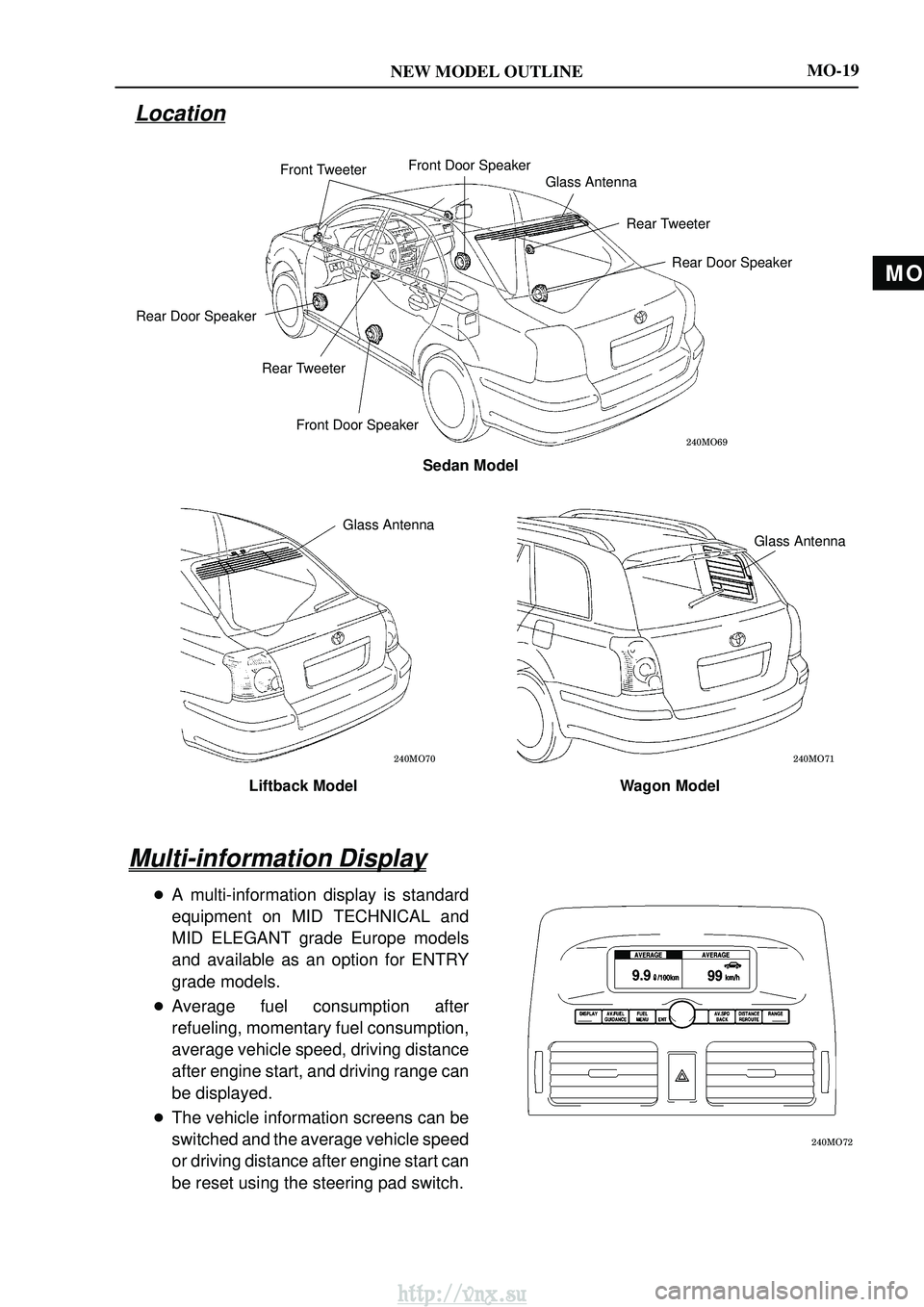
Front TweeterFront Door Speaker
Glass Antenna
Rear TweeterRear Door Speaker
Front Door Speaker
Rear Tweeter
Rear Door Speaker
Sedan Model
Glass Antenna
Liftback Model
Wagon Model
Glass Antenna
���\b ��
MO-19
Location
Multi-information Display
�A multi-information display is standard
equipment on MID TECHNICAL and
MID ELEGANT grade Europe models
and available as an option for ENTRY
grade models.
� Average fuel consumption after
refueling, momentary fuel consumption,
average vehicle speed, driving distance
after engine start, and driving range can
be displayed.
� The vehicle information screens can be
switched and the average vehicle speed
or driving distance after engine start can
be reset using the steering pad switch.
http://vnx.su
Page 21 of 2234
MO
NEW MODEL OUTLINE
���\b ��
���\b �� ���\b ��
Front TweeterFront Door Speaker
Glass Antenna
Rear TweeterRear Door Speaker
Front Door Speaker
Rear Tweeter
Rear Door Speaker
Sedan Model
Glass Antenna
Liftback Model
Wagon Model
Glass Antenna
���\b ��
MO-19
Location
Multi-information Display
�A multi-information display is standard
equipment on MID TECHNICAL and
MID ELEGANT grade Europe models
and available as an option for ENTRY
grade models.
� Average fuel consumption after
refueling, momentary fuel consumption,
average vehicle speed, driving distance
after engine start, and driving range can
be displayed.
� The vehicle information screens can be
switched and the average vehicle speed
or driving distance after engine start can
be reset using the steering pad switch.
http://vnx.su
Page 75 of 2234

(i)TORQUE WHEN USING TORQUE WRENCH WITH EX-
TENSION TOOL
(1)When the torque wrench")
L1L2L1L2L1L2
D02612
L2
L1L2
L1L2
L1
D01201
±
INTRODUCTIONREPAIR INSTRUCTION
01±9
AVENSIS REPAIR MANUAL (RM1018E)
(i)TORQUE WHEN USING TORQUE WRENCH WITH EX-
TENSION TOOL
(1)When the torque wrench is combined with SST oran extension tool to extend the length, and you
tighten until the torque wrench reads the specified
torque value, the actual torque becomes excessive.
(2)In this manual, only the specified torque is de-
scribed. In case of using SST or extension tool, cal-
culate the reading of the torque wrench by the fol-
lowing formula.
(3)Formula T'=T x L2/(L1 + L2)
T'Reading of torque wrench �N�m�kgf�cm�ft�lbf��
TTorque �N�m�kgf�cm�ft�lbf��
L1Length of SST or extension tool (cm)
L2Length of torque wrench (cm)
2.FOR VEHICLES EQUIPPED WITH SRS AIRBAG AND SEAT BELT PRETENSIONER
HINT:
The AVENSIS is equipped with an SRS (Supplemental Restraint System), which \
includes the driver airbag,
front passenger airbag and seat belt pretensioner.
Failure to carry out the service operations in the correct sequence could cause\
the supplemental restraint
system to unexpectedly deploy while servicing. This could cause a seriou\
s accident.
Furthermore, if a mistake is made when servicing the supplemental restra\
int system, it is possible that the
SRS will fail to operate when required. Before servicing (including remova\
l or installation of parts, inspection
or replacement), be sure to read the following items carefully. Then follow the correct procedures described
in this manual.
(a)GENERAL NOTICE (1)Malfunction symptoms of the supplemental restraint system are difficult to confirm so the diag-nostic trouble codes become the most important source of information when trou\
bleshooting.
When troubleshooting the supplemental restraint system, always check the dia\
gnostic trouble
codes before disconnecting the battery (See page 05±1184).
(2) Work must be started after 90 seconds from the time that the ignition switch\
is turned to the LOCK position and the negative (±) terminal cable is disconnected from the batte\
ry.
(The supplemental restraint system is equipped with a back±up power sourc\
e. So, if work is
started within 90 seconds after disconnecting the negative (±) terminal ca\
ble from the battery,
the SRS may deploy).
When the negative (±) terminal cable is disconnected from the battery, memory of the clock and
audio systems is cancelled. So, before starting work, make a record of the contents recorded
in each memory system. Then, when work is finished, reset the clock and audio systems as be-
fore.
http://vnx.su
Page 84 of 2234

NOTICE:
�Confirm that the VSC warning light blinks.
�VSC system will be reset when the engine is re-
started.
�Fasten the v")
01±18
±
INTRODUCTION REPAIR INSTRUCTION
AVENSIS REPAIR MANUAL (RM1018E)
NOTICE:
�Confirm that the VSC warning light blinks.
�VSC system will be reset when the engine is re-
started.
�Fasten the vehicle with lock chains.
(b) NOTICES OF RELATED OPERATIONS TO VSC (1) Do not carry out unnecessary installation and re-
moval as it might disorder the adjustment of related
parts to VSC.
(2) Be sure to carry out the preparation for operation and the confirmation of operation completion in ac-
cordance with the instruction of the text and when
the related operations to VSC are performed.
10. FOR VEHICLES EQUIPPED WITH CATALYTIC CONVERTER
CAUTION:
If a large amount of unburned gasoline flows into the converter, it may cause overheating and is a
fire hazard. To prevent this, observe the following precautions.
(a) Use only unleaded gasoline.
(b) Avoid prolonged idling. Avoid idling the engine for more than 20 minutes.
(c) Avoid a spark jump test. (1) Perform a spark jump test only when absolutely necessary. Perform this test as rapidly as pos-sible.
(2) While testing, never race the engine.
(d) Avoid a prolonged engine compression measurement. Engine compression measurements must be performed as rapidly as possible\
.
(e) Do not run the engine when the fuel tank is nearly empty. This may cause the engine to misfire and create an extra load on the converter.
http://vnx.su
Page 1313 of 2234
55±18
±
HEATER & AIR CONDITIONER COMBUSTION TYPE POWER HEATER SYSTEM
AVENSIS REPAIR MANUAL (RM1018E) DTC No.
Comment / Remedy
Description of fault
071Surface sensor break
Check connecting leads.
Resistance value between 4 and 11 at connector B > 2 �� (If
break)
072Surface sensor short±circuit
Check connecting leads.
Resistance value between 4 and 11 at connector B > 50 � (If
short±circuit)
090
092
093Control unit detective (Internal fault / Reset)
Control unit detective (ROM error)
Control unit detective (RAM error)
Control unit malfunction due to interference voltage from ve-
hicle electrical system;
possible causes low batteries, chargers, other sources of
interference; eliminate interference voltages.
Internal faults detected in microprocessor / memory detected.
Replace control unit.
097Internal control unit faultsOther faults which cannot lead to DTC No. 90, 92 and 93,
replace control unit.
http://vnx.su
Page 1446 of 2234
60±2
±
SUPPLEMENTAL RESTRAINT SYSTEM SUPPLEMENTAL RESTRAINT SYSTEM
AVENSIS REPAIR MANUAL (RM1018E)
�When the negative (±) terminal cable is disconnected from the batte\
ry, the memory of the clock
and audio system will be canceled. So before starting work, make a record o\
f the contents mem-
orized in the audio memory system. When work is finished, reset the audio syst\
ems as they
were before and adjust the clock. To avoid erasing the memory in each memory system, never
use a back±up power supply from outside the vehicle.
�If the vehicle is equipped with a mobile communication system, refer to the precaution in the
INTRODUCTION section.
http://vnx.su
Page 1554 of 2234

AUDIO & VISUAL SYSTEM
PRECAUTION
1. OBSERVE HANDLING AND OPERATIONAL PRECAUTIONS
(a) Please explain to")
670S4±01
±
AUDIO & VISUAL SYSTEM AUDIO & VISUAL SYSTEM
67±1
AVENSIS REPAIR MANUAL (RM1018E)
AUDIO & VISUAL SYSTEM
PRECAUTION
1. OBSERVE HANDLING AND OPERATIONAL PRECAUTIONS
(a) Please explain to the customer that when the negative terminal is disconnected from the batter\
y, the
channel information memory of the AM/FM broadcast stations in the radio receive\
r is cleared. If neces-
sary, make a note of the recorded channel information before the negative ter\
minal is disconnected,
then reset the information after the negative terminal is reconnected.
(b) The removal/installation of the radio receiver should be performed after al\
l the cassette tapes and au- dio CDs are ejected from the radio receiver.
HINT:
If the cassette tapes and the audio CDs cannot be ejected due to the malfu\
nction of the radio receiver, do
not try to drag them out by force. Bring the vehicle to the repair plant\
.
(c) Fasten the earth bolt securely when the antenna cord is removed or insta\
lled.
HINT:
Failing to fasten the earth bolt securely causes noise at the time of ra\
dio wave reception.
(d) Do not touch the cone paper of the speaker.
http://vnx.su

 DTC No.
Comment / Remedy
Description of fault
071Surface sensor break
Check connecting leads.
R")