Page 7 of 2234
MO
NEW MODEL OUTLINE
����\b��
����\b��
����\b��
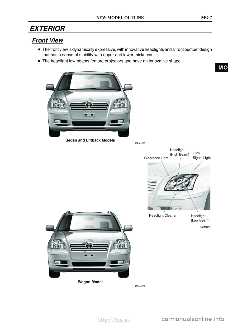
Sedan and Liftback Models
Wagon Model
Headlight
(High Beam)
Clearance Light Turn
Signal Light
Headlight Cleaner Headlight
(Low Beam)
MO-7
EXTERIOR
Front View
�The front view is dynamically expressive, with innovative headlights and\
a front bumper design
that has a sense of stability with upper and lower thickness.
� The headlight low beams feature projectors and have an innovative shape.\
http://vnx.su
Page 8 of 2234
NEW MODEL OUTLINE
����\b��
����\b��
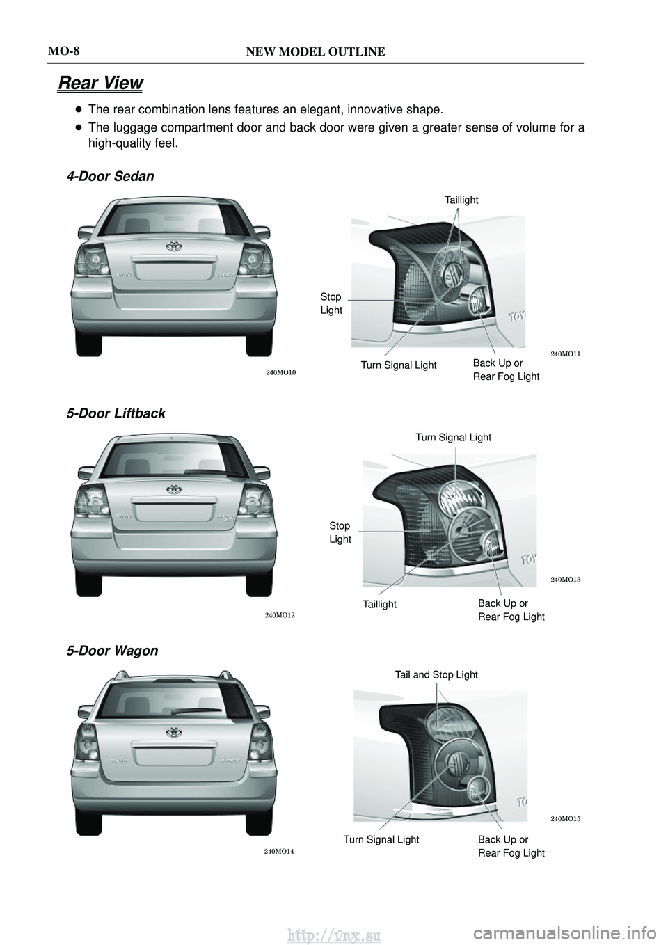
Taillight
Stop
Light Turn Signal Light Back Up or
Rear Fog Light
����\b��
����\b��
Turn Signal Light
Stop
Light Taillight Back Up or
Rear Fog Light
����\b��
����\b��
Tail and Stop Light
Turn Signal Light Back Up or Rear Fog Light
MO-8
Rear View
�The rear combination lens features an elegant, innovative shape.
� The luggage compartment door and back door were given a greater sense of\
volume for a
high-quality feel.
4-Door Sedan
5-Door Liftback
5-Door Wagon
http://vnx.su
Page 60 of 2234

SYMPTOM CONFIRMATION AND DIAGNOSTIC TROUBLE CODE
HINT:
�The diagnostic system in AVENSIS has various")
±
INTRODUCTION HOW TO TROUBLESHOOT ECU CONTROLLED
SYSTEMS01±25
AVENSIS REPAIR MANUAL (RM1018E)
SYMPTOM CONFIRMATION AND DIAGNOSTIC TROUBLE CODE
HINT:
�The diagnostic system in AVENSIS has various functions. The first function is the Diagnostic Trouble
Code (DTC) Check, in which a malfunction in the signal circuits to the ECU is stored in code form in
the ECU memory. Another function is the Input Signal Check, which checks if the signals from various
switches are sent to the ECU correctly. By using these check functions, it is possible to quickly narrow
down potential problem areas and troubleshooting can be performed effectively. The diagnostic func-
tions are incorporated in the following systems in the AVENSIS.
SystemDiagnostic Trouble
Code CheckInput Signal Check(Sensor Check)Diagnostic Test
Mode (Active Test)
SFI System (1AZ±FE/1AZ±FSE, 1ZZ±FE/3ZZ±FE)�
(with Check Mode)��
ECD System (1CD±FTV)�
(with Check Mode)��
ABS with EBD System���
ABS with EBD & BA & TRC & VSC System���
Electronically Controlled Automatic Transmission [ECT]�
(with Check Mode)�
Air Conditioning System��
Supplemental Restraint System�
Audio System�
Power Door Lock Control System��
Wireless Door Lock Control System�
Key Reminder Warning System�
Engine Immobiliser System��
Theft Deterrent System��
Multiplex Communication System�
Cruise Control System��
�In the DTC check, it is very important to determine whether the problem indicated by the DTC is still
occurring or has occurred in the past but returned to normal at present. In addit\
ion during the problem
symptom check, it a check must be made on whether the malfunction indicated by \
the DTC is directly
related to the problem symptom or not. For this reason, the DTC should be checked before and after
symptom confirmation to determine the current conditions. If this is not done, \
it may, depending on the
case, result in unnecessary troubleshooting for systems that are operati\
ng normally. This would make
more difficult to detect the problem area or to try to repair irrelevant areas. \
Therefore, always follow
the procedures in the correct order and perform the DTC check.
�A flow chart showing how to proceed with troubleshooting using the diagnostic trouble\
code (DTC)
check is shown the this page. This flow chart shows how to utilize the DTC check effectively. Then,
by carefully checking the results, this chart indicates how to proceed either to the DTC troubleshooting
or to the troubleshooting of the problem symptoms table.
1 DTC check
2 Make a note of DTCs displayed and then clear the memory
3 Symptom confirmation
http://vnx.su
Page 273 of 2234
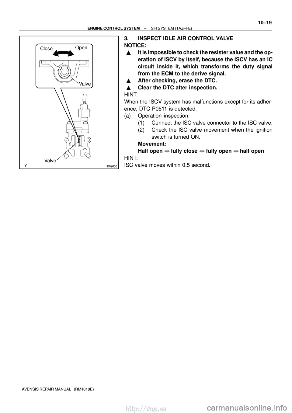
CloseOpen
Valve
Valve
B09650
±
ENGINE CONTROL SYSTEM SFI SYSTEM (1AZ±FE)
10±19
AVENSIS REPAIR MANUAL (RM1018E)
3. INSPECT IDLE AIR CONTROL VALVE
NOTICE:
�It is impossible to check the resister value and the op-
eration of ISCV by itself, because the ISCV has an IC
circuit inside it, which transforms the duty signal
from the ECM to the derive signal.
�After checking, erase the DTC.
�Clear the DTC after inspection.
HINT:
When the ISCV system has malfunctions except for its adher-
ence, DTC P0511 is detected.
(a) Operation inspection. (1) Connect the ISC valve connector to the ISC valve.
(2) Check the ISC valve movement when the ignitionswitch is turned ON.
Movement:
Half open �fully close � fully open � half open
HINT:
ISC valve moves within 0.5 second.
http://vnx.su
Page 284 of 2234
A60620
Close
Open
Valve
VaIve
Open
Close
Valve
1ZZ±FE:
3ZZ±FE: VaIve
10±2
±
ENGINE CONTROL SYSTEM SFI SYSTEM (1ZZ±FE/3ZZ±FE)
AVENSIS REPAIR MANUAL (RM1018E)
3. INSPECT IDLE AIR CONTROL VALVE
NOTICE:
�It is impossible to check the resister value and the op-
eration of ISCV by itself, because the ISCV has an IC
circuit inside it, which transforms the duty signal
from the ECM to the derive signal.
�Clear the DTC after inspection.
HINT:
When the ISCV system has malfunctions except for its adher-
ence, DTC P0505 is detected.
(a) Operation inspection. (1) Connect the ISCV connector to the ISCV.
(2) Check the valve movement when the ignition switch
is turned ON.
Movement:
Half open �fully close � fully open � half open
HINT:
ISCV moves within 0.5 second.
http://vnx.su
Page 598 of 2234

14±101
AVENSIS REPAIR MANUAL (RM1018E)
ENGINE(1AZ±FE)
INSPECTION
1.INSPECT COOLANT (See page 16±13)
2.INSPECT ENGINE OIL (See page")
140D1±02
CG
TCA51075
A52004
±
ENGINE MECHANICALENGINE(1AZ±FE)
14±101
AVENSIS REPAIR MANUAL (RM1018E)
ENGINE(1AZ±FE)
INSPECTION
1.INSPECT COOLANT (See page 16±13)
2.INSPECT ENGINE OIL (See page 17±6)
3. INSPECT BATTERY
Standard specific gravity: 1.25 to 1.29 at 20� C (68�F)
4. INSPECT AIR CLEANER FILTER ELEMENT SUB±ASSY
5.INSPECT SPARK PLUG (See page 18±9)
6. INSPECT V±RIBBED BELT
7. INSPECT IGNITION TIMING
(a) Warm up engine.
(b) When using hand±held tester:(1) Connect the hand±held tester to the DLC3.
(2) Enter DATA LIST MODE on the hand±held tester.
Ignition timing: 8 to 12 � BTDC
HINT:
Please refer to the hand±held tester operator's manual if you
need help to select DATA LIST.
(c) When not using hand±held tester:
(1) Using SST, connect terminals 13 (TC) and 4 (CG)of DLC3.
SST 09843±18040
NOTICE:
�Make sure of the terminal numbers before connecting
them. Connection with a wrong terminal can damage
the engine.
�Turn OFF all electrical systems before connecting the
terminals.
�Operate the inspection after the cooling fan motor is
turned OFF.
(2) Remove the cylinder head cover No.2.
(3) Pull out the wire harness as shown in the illustration.
Connect the clip of the timing light to the engine.
NOTICE:
�Use a timing light which detects the first signal.
�After checking, be sure to wrap the wire harness with
tape.
(4) Inspect ignition timing at idle.
Ignition timing: 8 to 12 � BTDC
NOTICE:
When checking the ignition timing, shift the transmission
to the neutral position.
HINT:
Run the engine at 1,000 to 1,300 rpm for 5 seconds, check that
the engine rpm returns to the idle speed.
http://vnx.su
Page 602 of 2234

14±181
AVENSIS REPAIR MANUAL (RM1018E)
ENGINE(1AZ±FSE)
INSPECTION
1.INSPECT COOLANT (See page 16±25)
2.INSPECT ENGINE OIL(See pag")
141CP±01
CG
TCA51075
A79034
±
ENGINE MECHANICALENGINE(1AZ±FSE)
14±181
AVENSIS REPAIR MANUAL (RM1018E)
ENGINE(1AZ±FSE)
INSPECTION
1.INSPECT COOLANT (See page 16±25)
2.INSPECT ENGINE OIL(See page 17±13)
3.INSPECT BATTERY
Standard specific gravity: 1.25 to 1.29 at 20�C (68�F)
4.INSPECT AIR CLEANER FILTER ELEMENT SUB±ASSY
5.INSPECT SPARK PLUG (See page 18±14)
6.INSPECT V±RIBBED BELT
7.INSPECT IGNITION TIMING
(a)Warm up engine.
(b)When using hand±held tester:(1)Connect the hand±held tester to the DLC3.
(2)Enter DATA LIST MODE on the hand±held tester.
Ignition timing: 8 to 12� BTDC
HINT:
Please refer to the hand±held tester operator's manual if you
need help to select DATA LIST.
(c) When not using hand±held tester:
(1) Using SST, connect terminals 13 (TC) and 4 (CG)of DLC3.
SST 09843±18040, 09843±18020
NOTICE:
�Make sure of the terminal numbers before connecting
them. Connection with a wrong terminal can damage
the engine.
�Turn OFF all electrical systems before connecting the
terminals.
�Operate the inspection after the cooling fan motor is
turned OFF
(2) Remove the cylinder head cover No.2.
(3) Pull out the wire harness as shown in the illustration.
Connect the clip of the timing light to the engine.
NOTICE:
�Use a timing light which detects the first signal.
�After checking, be sure to wrap the wire harness with
tape.
(4) Inspect ignition timing at idle.
Ignition timing: 8 to 12 � BTDC
NOTICE:
When checking the ignition timing, shift the transmission
to the neutral position.
HINT:
Run the engine at 1,000 to 1,300 rpm for 5 seconds, check that
the engine rpm returns to the idle speed. (5) Disconnect terminals 13 (TC) and 4 (CG) of DLC3.
http://vnx.su
Page 609 of 2234

14±1
AVENSIS REPAIR MANUAL (RM1018E)
ENGINE(1ZZ±FE/3ZZ±FE)
INSPECTION
1.INSPECT COOLANT (See page 16±1)
2.INSPECT ENGINE")
140KR±02
A62199
TCCG
A62200
±
ENGINE MECHANICALENGINE(1ZZ±FE/3ZZ±FE)
14±1
AVENSIS REPAIR MANUAL (RM1018E)
ENGINE(1ZZ±FE/3ZZ±FE)
INSPECTION
1.INSPECT COOLANT (See page 16±1)
2.INSPECT ENGINE OIL (See page 17±1)
3.INSPECT BATTERY (See page 19±5)
4.INSPECT AIR CLEANER FILTER ELEMENT SUB±ASSY
5.INSPECT SPARK PLUG (See page 18±3)
6.INSPECT FAN AND GENERATOR V BELT
HINT:
You don't need to check the belt deflection because auto tensioner is ado\
pted.
7.INSPECT IGNITION TIMING
(a)Warm up engine.
(b)When using hand±held tester:
(1)Connect the hand±held tester to the DLC3.
(2)Enter DATA LIST MODE on the hand±held tester.
Ignition timing: 8 to 12�BTDC
HINT:
Please refer to the hand±held tester operator's manual if you
need help to select DATA LIST.
(c) When not using hand±held tester: (1) Using SST, connect terminal 13 (TC) and 4 (CG) ofthe DLC3.
SST 09843±18040
NOTICE:
�Make sure of the terminal numbers before connecting
them. Connection with a wrong terminal can damage
the engine.
�Turn OFF all electrical systems before connecting the
terminals.
�Operate the inspection after the cooling fan motor is
turned OFF
(2) Remove the 2 nuts, and 2 clips, and then remove the cylinder head cover.
(3) Pull out the wire harness as shown in the illustration.
(4) Connect the clip of the timing light to the engine.
NOTICE:
�Use a timing light which detects the first signal.
�After checking, be sure to wrap the wire harness with
tape.
http://vnx.su

AVENSIS REPAIR MANUAL (RM1018E)
3. INSPECT IDLE AIR CONTROL VALVE
N")