Page 1807 of 3502
![NISSAN TEANA 2003 Service Manual DTC P0340, P0345 CMP SENSOR (PHASE)
EC-525
[VQ]
C
D
E
F
G
H
I
J
K
L
MA
EC
DTC Confirmation ProcedureBBS00514
NOTE:
If DTC Confirmation Procedure has been previously conducted, always turn ignition s](/manual-img/5/57392/w960_57392-1806.png "NISSAN TEANA 2003 Service Manual DTC P0340, P0345 CMP SENSOR (PHASE)
EC-525
[VQ]
C
D
E
F
G
H
I
J
K
L
MA
EC
DTC Confirmation ProcedureBBS00514
NOTE:
If DTC Confirmation Procedure has been previously conducted, always turn ignition s")
DTC P0340, P0345 CMP SENSOR (PHASE)
EC-525
[VQ]
C
D
E
F
G
H
I
J
K
L
MA
EC
DTC Confirmation ProcedureBBS00514
NOTE:
If DTC Confirmation Procedure has been previously conducted, always turn ignition switch OFF and wait at
least 10 seconds before conducting the next test.
TESTING CONDITION:
Before performing the following procedure, confirm that battery voltage is more than 10.5V with igni-
tion switch ON.
WITH CONSULT-II
1. Turn ignition switch ON.
2. Select “DATA MONITOR” mode with CONSULT-II.
3. Crank engine for at least 2 seconds and run it for at least 5 sec-
onds at idle speed.
4. If 1st trip DTC is detected, go to EC-529, "
Diagnostic Procedure"
.
If 1st trip DTC is not detected, go to next step.
5. Maintaining engine speed at more than 800 rpm for at least 5
seconds.
6. If 1st trip DTC is detected, go to EC-529, "
Diagnostic Procedure"
.
WITHOUT CONSULT-II
1. Crank engine for at least 2 seconds and run it for at least 5 seconds at idle speed.
2. Turn ignition switch OFF, wait at least 10 seconds and then turn ON.
3. Perform Diagnostic Test Mode II (Self-diagnostic results) with ECM.
4. If 1st trip DTC is detected, go to EC-529, "
Diagnostic Procedure" .
If 1st trip DTC is not detected, go to next step.
5. Start engine and maintaining engine speed at more than 800 rpm for at least 5 seconds.
6. Turn ignition switch OFF, wait at least 10 seconds and then turn ON.
7. Perform Diagnostic Test Mode II (Self-diagnostic results) with ECM.
8. If 1st trip DTC is detected, go to EC-529, "
Diagnostic Procedure" .
SEF058Y
Page 1808 of 3502
EC-526
[VQ]
DTC P0340, P0345 CMP SENSOR (PHASE)
Wiring DiagramBBS00515
BANK 1
TBWM1450E
Page 1809 of 3502
![NISSAN TEANA 2003 Service Manual DTC P0340, P0345 CMP SENSOR (PHASE)
EC-527
[VQ]
C
D
E
F
G
H
I
J
K
L
MA
EC
Specification data are reference values and are measured between each terminal and ground.
Pulse signal is measured by CONSU](/manual-img/5/57392/w960_57392-1808.png "NISSAN TEANA 2003 Service Manual DTC P0340, P0345 CMP SENSOR (PHASE)
EC-527
[VQ]
C
D
E
F
G
H
I
J
K
L
MA
EC
Specification data are reference values and are measured between each terminal and ground.
Pulse signal is measured by CONSU")
DTC P0340, P0345 CMP SENSOR (PHASE)
EC-527
[VQ]
C
D
E
F
G
H
I
J
K
L
MA
EC
Specification data are reference values and are measured between each terminal and ground.
Pulse signal is measured by CONSULT-II.
CAUTION:
Do not use ECM ground terminals when measuring input/output voltage. Doing so may result in dam-
age to the ECM's transistor. Use a ground other than ECM terminals, such as the ground.
: Average voltage for pulse signal (Actual pulse signal can be confirmed by oscilloscope.)TER-
MINAL
NO.WIRE
COLORITEM CONDITION DATA (DC Voltage)
33 WCamshaft position sensor
(PHASE) (Bank 1)[Engine is running]
�Warm-up condition
�Idle speed
NOTE:
The pulse cycle changes depending on rpm at
idle.1.0 - 4.0V
[Engine is running]
�Engine speed: 2,000 rpm1.0 - 4.0V
111 W / BECM relay
(Self shut-off)[Engine is running]
[Ignition switch: OFF]
�For a few seconds after turning ignition
switch OFF0 - 1.0V
[Ignition switch: OFF]
�More than a few seconds after turning igni-
tion switch OFFBATTERY VOLTAGE
(11 - 14V)
11 9
120R/G
R/GPower supply for ECM[Ignition switch: ON]BATTERY VOLTAGE
(11 - 14V)
PBIB1039E
PBIB1040E
Page 1810 of 3502
EC-528
[VQ]
DTC P0340, P0345 CMP SENSOR (PHASE)
BANK 2
TBWM1451E
Page 1811 of 3502
![NISSAN TEANA 2003 Service Manual DTC P0340, P0345 CMP SENSOR (PHASE)
EC-529
[VQ]
C
D
E
F
G
H
I
J
K
L
MA
EC
Specification data are reference values and are measured between each terminal and ground.
Pulse signal is measured by CONSU](/manual-img/5/57392/w960_57392-1810.png "NISSAN TEANA 2003 Service Manual DTC P0340, P0345 CMP SENSOR (PHASE)
EC-529
[VQ]
C
D
E
F
G
H
I
J
K
L
MA
EC
Specification data are reference values and are measured between each terminal and ground.
Pulse signal is measured by CONSU")
DTC P0340, P0345 CMP SENSOR (PHASE)
EC-529
[VQ]
C
D
E
F
G
H
I
J
K
L
MA
EC
Specification data are reference values and are measured between each terminal and ground.
Pulse signal is measured by CONSULT-II.
CAUTION:
Do not use ECM ground terminals when measuring input/output voltage. Doing so may result in dam-
age to the ECM's transistor. Use a ground other than ECM terminals, such as the ground.
: Average voltage for pulse signal (Actual pulse signal can be confirmed by oscilloscope.)
Diagnostic ProcedureBBS00516
1. CHECK STARTING SYSTEM
Turn ignition switch to START position.
Ye s o r N o
Ye s > > G O T O 2 .
No >> Check starting system. (Refer to SC-14, "
STARTING SYSTEM" .)
TER-
MINAL
NO.WIRE
COLORITEM CONDITION DATA (DC Voltage)
14 WCamshaft position sensor
(PHASE) (Bank 2)[Engine is running]
�Warm-up condition
�Idle speed
NOTE:
The pulse cycle changes depending on rpm at
idle.1.0 - 4.0V
[Engine is running]
�Engine speed: 2,000 rpm1.0 - 4.0V
111 W / BECM relay
(Self shut-off)[Engine is running]
[Ignition switch: OFF]
�For a few seconds after turning ignition
switch OFF0 - 1.0V
[Ignition switch: OFF]
�More than a few seconds after turning igni-
tion switch OFFBATTERY VOLTAGE
(11 - 14V)
11 9
120R/G
R/GPower supply for ECM[Ignition switch: ON]BATTERY VOLTAGE
(11 - 14V)
PBIB1039E
PBIB1040E
Does the engine turn over?
Does the starter motor operate?
Page 1812 of 3502
EC-530
[VQ]
DTC P0340, P0345 CMP SENSOR (PHASE)
2. CHECK GROUND CONNECTIONS
1. Turn ignition switch OFF.
2. Loosen and retighten two ground screws on the body.
Refer to EC-457, "
Ground Inspection" .
OK or NG
OK >> GO TO 3.
NG >> Repair or replace ground connections.
3. CHECK CAMSHAFT POSITION (CMP) SENSOR (PHASE) POWER SUPPLY CIRCUIT
1. Disconnect camshaft position (CMP) sensor (PHASE) harness connector.
2. Turn ignition switch ON.
3. Check voltage between CMP sensor (PHASE) terminal 3 and
ground with CONSULT-II or tester.
OK or NG
OK >> GO TO 5.
NG >> GO TO 4.
PBIB2160E
Voltage: Battery voltage
PBIB2180E
SEF481Y
Page 1813 of 3502
![NISSAN TEANA 2003 Service Manual DTC P0340, P0345 CMP SENSOR (PHASE)
EC-531
[VQ]
C
D
E
F
G
H
I
J
K
L
MA
EC
4. DETECT MALFUNCTIONING PART
Check the following.
�Harness connectors E11, E253
�Harness connectors E102, M57
�Harness conn](/manual-img/5/57392/w960_57392-1812.png "NISSAN TEANA 2003 Service Manual DTC P0340, P0345 CMP SENSOR (PHASE)
EC-531
[VQ]
C
D
E
F
G
H
I
J
K
L
MA
EC
4. DETECT MALFUNCTIONING PART
Check the following.
�Harness connectors E11, E253
�Harness connectors E102, M57
�Harness conn")
DTC P0340, P0345 CMP SENSOR (PHASE)
EC-531
[VQ]
C
D
E
F
G
H
I
J
K
L
MA
EC
4. DETECT MALFUNCTIONING PART
Check the following.
�Harness connectors E11, E253
�Harness connectors E102, M57
�Harness connectors F103, M52
�Harness for open or short between camshaft position sensor (PHASE) and ECM
�Harness for open or short between camshaft position sensor (PHASE) and IPDM E/R
>> Repair open circuit or short to ground or short to power in harness or connectors.
5. CHECK CMP SENSOR (PHASE) GROUND CIRCUIT FOR OPEN AND SHORT
1. Turn ignition switch OFF.
2. Check harness continuity between CMP sensor (PHASE) terminal 1 and ground.
Refer to Wiring Diagram.
3. Also check harness for short to power.
OK or NG
OK >> GO TO 7.
NG >> GO TO 6.
6. DETECT MALFUNCTIONING PART
Check the following.
�Harness connectors F103, M12
�Harness for open or short between CMP sensor (PHASE) and ground
>> Repair open circuit or short to power in harness or connectors.
7. CHECK CMP SENSOR (PHASE) INPUT SIGNAL CIRCUIT FOR OPEN AND SHORT
1. Disconnect ECM harness connector.
2. Check harness continuity between ECM terminal 33 (bank1) or 14 (bank2) and CMP sensor (PHASE) ter-
minal 2. Refer to Wiring Diagram.
3. Also check harness for short to ground and short to power.
OK or NG
OK >> GO TO 8.
NG >> Repair open circuit or short to ground or short to power in harness or connectors.
8. CHECK CAMSHAFT POSITION SENSOR (PHASE)
Refer to EC-532, "
Component Inspection" .
OK or NG
OK >> GO TO 9.
NG >> Replace camshaft position sensor (PHASE).Continuity should exist.
Continuity should exist.
Page 1814 of 3502
EC-532
[VQ]
DTC P0340, P0345 CMP SENSOR (PHASE)
9. CHECK CAMSHAFT (INTAKE)
Check the following.
�Accumulation of debris to the signal plate of camshaft rear end
�Chipping signal plate of camshaft rear end
OK or NG
OK >> GO TO 10.
NG >> Remove debris and clean the signal plate of camshaft
rear end or replace camshaft.
10. CHECK INTERMITTENT INCIDENT
Refer to EC-450, "
TROUBLE DIAGNOSIS FOR INTERMITTENT INCIDENT" .
>>INSPECTION END
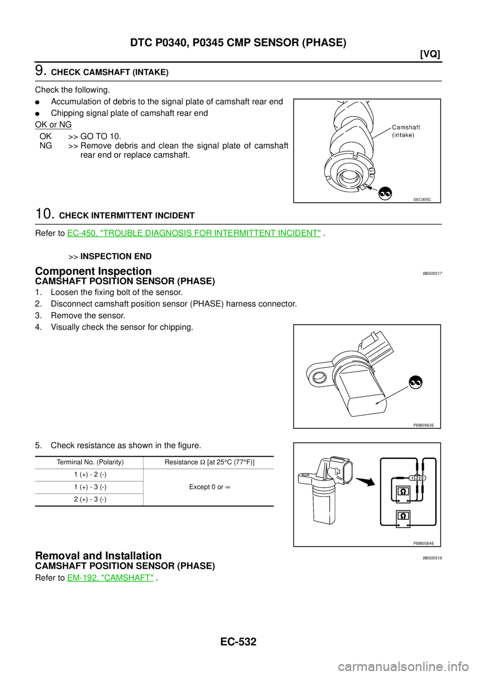
Component InspectionBBS00517
CAMSHAFT POSITION SENSOR (PHASE)
1. Loosen the fixing bolt of the sensor.
2. Disconnect camshaft position sensor (PHASE) harness connector.
3. Remove the sensor.
4. Visually check the sensor for chipping.
5. Check resistance as shown in the figure.
Removal and InstallationBBS00518
CAMSHAFT POSITION SENSOR (PHASE)
Refer to EM-192, "CAMSHAFT" .
SEC905C
PBIB0563E
Terminal No. (Polarity) Resistance Ω [at 25°C (77°F)]
1 (+) - 2 (-)
Except 0 or ∞ 1 (+) - 3 (-)
2 (+) - 3 (-)
PBIB0564E
![NISSAN TEANA 2003 Service Manual EC-526
[VQ]
DTC P0340, P0345 CMP SENSOR (PHASE)
Wiring DiagramBBS00515
BANK 1
TBWM1450E](/manual-img/5/57392/w960_57392-1807.png "NISSAN TEANA 2003 Service Manual EC-526
[VQ]
DTC P0340, P0345 CMP SENSOR (PHASE)
Wiring DiagramBBS00515
BANK 1
TBWM1450E")
![NISSAN TEANA 2003 Service Manual EC-528
[VQ]
DTC P0340, P0345 CMP SENSOR (PHASE)
BANK 2
TBWM1451E](/manual-img/5/57392/w960_57392-1809.png "NISSAN TEANA 2003 Service Manual EC-528
[VQ]
DTC P0340, P0345 CMP SENSOR (PHASE)
BANK 2
TBWM1451E")
![NISSAN TEANA 2003 Service Manual EC-530
[VQ]
DTC P0340, P0345 CMP SENSOR (PHASE)
2. CHECK GROUND CONNECTIONS
1. Turn ignition switch OFF.
2. Loosen and retighten two ground screws on the body.
Refer to EC-457, "
Ground Inspection"](/manual-img/5/57392/w960_57392-1811.png "NISSAN TEANA 2003 Service Manual EC-530
[VQ]
DTC P0340, P0345 CMP SENSOR (PHASE)
2. CHECK GROUND CONNECTIONS
1. Turn ignition switch OFF.
2. Loosen and retighten two ground screws on the body.
Refer to EC-457, \"
Ground Inspection\"")