Page 354 of 3502
AT-346
ASSEMBLY
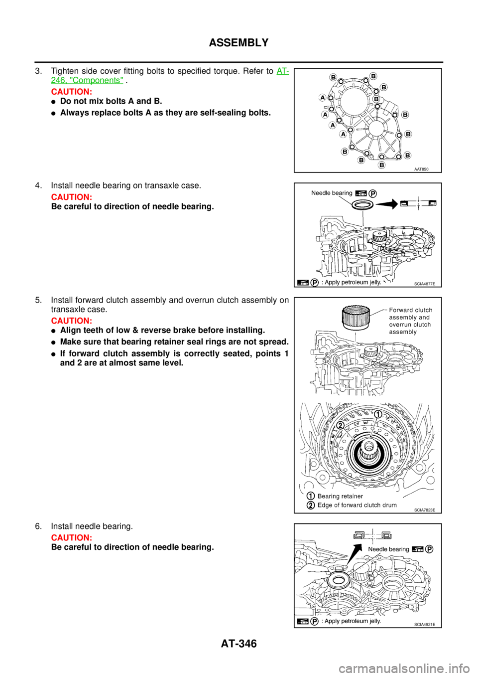
3. Tighten side cover fitting bolts to specified torque. Refer to AT-
246, "Components" .
CAUTION:
�Do not mix bolts A and B.
�Always replace bolts A as they are self-sealing bolts.
4. Install needle bearing on transaxle case.
CAUTION:
Be careful to direction of needle bearing.
5. Install forward clutch assembly and overrun clutch assembly on
transaxle case.
CAUTION:
�Align teeth of low & reverse brake before installing.
�Make sure that bearing retainer seal rings are not spread.
�If forward clutch assembly is correctly seated, points 1
and 2 are at almost same level.
6. Install needle bearing.
CAUTION:
Be careful to direction of needle bearing.
AAT850
SCIA4877E
SCIA7823E
SCIA4921E
Page 356 of 3502
AT-348
ASSEMBLY
b. Install rear sun gear on rear planetary carrier.
CAUTION:
Be careful to direction of rear sun gear.
c. Install rear planetary carrier (with rear sun gear) on transaxle
case.
11. Install needle bearing on front planetary carrier, then install them
together on transaxle case.
CAUTION:
Be careful to direction of needle bearing.
12. Install low & reverse brake piston according to the following pro-
cedures.
a. Set and align return springs (spring retainer) to transaxle case
gutters as shown in figure.
b. Set and align low & reverse brake piston with retainer.
CAUTION:
Apply ATF to surface of low & reverse brake piston and
retainer.
SAT027F
SAT026F
SCIA4923E
SAT322F
SCIA3652E
Page 357 of 3502
ASSEMBLY
AT-349
D
E
F
G
H
I
J
K
L
MA
B
AT
c. Install low & reverse brake piston and retainer on transaxle
case.
CAUTION:
Align bracket to specified gutter as indicated in figure.
d. Make sure that each protrusion of low & reverse brake piston is
correctly set to corresponding return spring as follows.
�Push low & reverse brake piston and retainer evenly and
confirm they move smoothly.
�If they cannot move smoothly, remove low & reverse
brake piston and retainer assembly and align return
spring correctly as instructed in step “a”.
e. Push down low & reverse brake piston and retainer and install
snap ring.
13. Install low one-way clutch to front planetary carrier by turning
carrier in direction of arrow shown.
SCIA7824E
SCIA7825E
SCIA7826E
SAT206F
Page 360 of 3502
AT-352
ASSEMBLY
18. Install reverse clutch assembly on input shaft assembly (high
clutch drum).
Adjustment (2)BCS001OZ
When any parts listed below are replaced, adjust total end play and reverse clutch end play.
TOTAL END PLAY
�Measure clearance between reverse clutch drum and needle
bearing for oil pump cover.
�Select proper thickness of bearing race so that end play is within
specifications.
1. Measure dimensions “K” and “L” and then calculate dimension
“J”.
SCIA4461E
Part name Total end play Reverse clutch end play
transaxle case��
Overrun clutch hub��
Rear internal gear��
Rear planetary carrier��
Rear sun gear��
Front planetary carrier��
Front sun gear��
High clutch hub��
Input shaft assembly (high clutch drum)��
Oil pump cover��
Reverse clutch drum —�
SCIA3661E
SCIA3662E
Page 362 of 3502
AT-354
ASSEMBLY
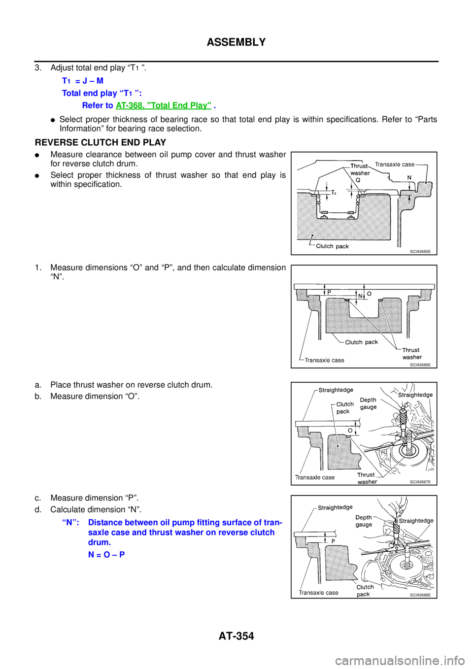
3. Adjust total end play “T1 ”.
�Select proper thickness of bearing race so that total end play is within specifications. Refer to “Parts
Information” for bearing race selection.
REVERSE CLUTCH END PLAY
�Measure clearance between oil pump cover and thrust washer
for reverse clutch drum.
�Select proper thickness of thrust washer so that end play is
within specification.
1. Measure dimensions “O” and “P”, and then calculate dimension
“N”.
a. Place thrust washer on reverse clutch drum.
b. Measure dimension “O”.
c. Measure dimension “P”.
d. Calculate dimension “N”.T
1 = J – M
Total end play “T
1 ”:
Refer to AT- 3 6 8 , "
Total End Play" .
SCIA3665E
SCIA3666E
SCIA3667E
“N”: Distance between oil pump fitting surface of tran-
saxle case and thrust washer on reverse clutch
drum.
N = O – P
SCIA3668E
Page 363 of 3502
ASSEMBLY
AT-355
D
E
F
G
H
I
J
K
L
MA
B
AT
2. Measure dimensions “R” and “S”, and then calculate dimension
“Q”.
a. Measure dimension “R”.
b. Measure dimension “S”.
c. Calculate dimension “Q”.
3. Adjust reverse clutch end play “T
2 ”.
�Select proper thickness of thrust washer so that reverse clutch end play is within specifications. Refer
to “Parts Information” for thrust washer selection.
Assembly (3)BCS001P0
1. Install anchor end pin and lock nut on transaxle case.
CAUTION:
Do not reuse anchor end pin.
2. Place brake band and strut on outside of reverse clutch drum.
Tighten anchor end pin just enough so that brake band is evenly
fitted on reverse clutch drum.
SAT384D
SAT385D
“Q”: Distance between transaxle case fitting sur-
face and thrust washer mating surface.
Q = R – S
SAT386D
T2 = N – Q
Reverse clutch end play:
Refer to AT- 3 6 8 , "
Reverse Clutch End Play" .
SAT196F
Page 364 of 3502
AT-356
ASSEMBLY
3. Place bearing race selected in total end play adjustment step on
oil pump cover.
4. Place thrust washer selected in reverse clutch end play step on
reverse clutch drum.
5. Install oil pump assembly and gasket on transaxle case.
CAUTION:
�Do not reuse gasket.
�Completely remove all moisture, oil and old sealant, etc.
from the transaxle case and converter housing mounting
surfaces.
6. Tighten oil pump fitting bolts to the specified torque. Refer to AT-
246, "Components" .
7. Install O-ring to input shaft assembly (high clutch drum).
8. Adjust brake band according to the following procedures.
a. Tighten anchor end pin to the specified torque.
b. Back off anchor end pin two and a half turns.
c. While holding anchor end pin, tighten lock nut. Refer to AT- 3 6 7 ,
"BRAKE BAND" .
9. Apply compressed air to oil holes of transaxle case and check
operation of brake band.
SCIA3629E
SCIA2980E
SCIA4928E
: 4.9 N·m (0.50 kg-m, 43 in-lb)
SCIA4869E
SAT397D
Page 366 of 3502
AT-358
ASSEMBLY
17. Install accumulator piston according to the following procedures.
a. Install O-rings on accumulator piston. Refer to AT- 3 6 5 , "
O-
RINGS" .
b. Install accumulator pistons and return springs on transaxle case.
Refer to AT- 3 6 5 , "
RETURN SPRINGS" .
CAUTION:
Apply ATF to inner surface of transaxle case.
18. Install lip seals for band servo oil holes on transaxle case.
19. Install low & reverse brake tube and oil sleeve. Tighten Low &
reverse brake tube bolts to the specified torque. Refer to AT-
246, "Components" .
20. Install control valve assembly according to the following proce-
dures.
a. Install O-ring on terminal body.
CAUTION:
�Do not reuse O-ring.
�Apply ATF to O-ring.
b. Insert manual valve into control valve assembly.
CAUTION:
Apply ATF to manual valve.
SCIA3303E
SCIA3304E
SCIA4867E
SCIA4868E
SCIA3999E
 on transaxle
case.
11. I")

.
Adjustment (2)BCS001OZ
When any parts listed below are replaced, adjust total end play and reverse clu")