Page 305 of 3502

REPAIR FOR COMPONENT PARTS
AT-297
D
E
F
G
H
I
J
K
L
MA
B
AT
4. Set SST on spring retainer, and remove snap ring from reverse
clutch drum while compressing return spring.
CAUTION:
�Set SST directly over return spring.
�Do not expand snap ring excessively.
5. Remove spring retainer and return spring from reverse clutch
drum.
6. Remove reverse clutch piston from reverse clutch drum by turn-
ing it.
7. Remove D-ring and seal lip from reverse clutch piston.
INSPECTION
Reverse Clutch Snap Rings, Return Spring and Spring Retainer
Check for deformation, fatigue or damage. Replace if necessary.
Reverse Clutch Drive Plates
�Check facing for burns, cracks or damage. Replace if necessary.
�Measure thickness of facing.
CAUTION:
�Measure the thickness at 3 locations and find the aver-
age.
�Inspect all drive plates.
�Replace if the thickness is below the allowable limit.
Reverse Clutch Dish Plates
�Check for damage or wear.
�Measure thickness of dish plate. Replace if damaged, worn or
deformed.
Reverse Clutch Piston
�Make sure that check balls are not fixed.
�Apply compressed air to check ball oil hole opposite return spring. Make sure there is no air leakage.
�Apply compressed air to oil hole on return spring side to make sure that air leaks past ball.
SCIA7795E
SCIA3319E
Thickness of drive plate
Standard and allowable limit:
Refer to AT- 3 6 6 , "
REVERSE CLUTCH" .
SAT162D
Thickness of dish plate: 2.96 mm (0.1165 in)
SAT163D
Page 306 of 3502
AT-298
REPAIR FOR COMPONENT PARTS
ASSEMBLY
1. Install D-ring (1) and seal lip (2) on reverse clutch piston (3).
CAUTION:
Be careful to direction of seal lip (2).
2. Install reverse clutch piston by reverse clutch drum by turning it
slowly.
CAUTION:
Apply ATF to inner surface of reverse clutch drum.
3. Install return spring and spring retainer on reverse clutch piston.
4. Set SST on spring retainer, and install snap ring while com-
pressing return spring.
CAUTION:
�Set SST directly over return spring.
�Do not expand snap ring excessively.
SCIA7812E
SCIA3319E
SCIA7795E
Page 307 of 3502
REPAIR FOR COMPONENT PARTS
AT-299
D
E
F
G
H
I
J
K
L
MA
B
AT
5. Install drive plates, driven plates, retaining plate and dish plates.
Refer to AT- 3 6 6 , "
REVERSE CLUTCH" .
CAUTION:
Be careful to order of plates.
NOTE:
Install two dish plates fitting each installation direction with
reverse clutch drum groove displaced slightly.
6. Install snap ring with a flat-bladed screwdriver.
SCIA4888E
SAT254E
SCIA4886E
Page 308 of 3502
AT-300
REPAIR FOR COMPONENT PARTS
7. Measure clearance between retaining plate and snap ring with
feeler gauge. If not within allowable limit, select proper retaining
plate. Refer to “Parts Information” for retaining plate selection.
8. Check operation of reverse clutch. Refer to AT- 2 9 6 , "
DISAS-
SEMBLY" . Standard and allowable limit:
Refer to AT- 3 6 6 , "
REVERSE CLUTCH" .
SCIA3321E
SCIA3316E
Page 323 of 3502
REPAIR FOR COMPONENT PARTS
AT-315
D
E
F
G
H
I
J
K
L
MA
B
AT
Low & Reverse BrakeBCS001OR
COMPONENTS
DISASSEMBLY
1. Check operation of low & reverse brake.
a. Apply compressed air to oil hole of transaxle case.
b. Check to see that retaining plate moves to snap ring.
c. If retaining plate does not contact snap ring:
�D-ring might be damaged.
�Fluid might be leaking past piston check ball.
2. Remove snap ring with flat-bladed screwdriver.
3. Remove low & reverse brake piston (with retainer) and spring
retainer from transaxle case.
4. Remove snap ring with flat-bladed screwdriver.
5. Remove driven plates, drive plates, retaining plates and dish
plates from transaxle case.
1. Driven plate 2. Dish plate 3. Snap ring
4. Spring retainer 5. D-ring 6. D-ring
7. Low & reverse brake piston 8. Retainer 9. Snap ring
10. Retaining plate 11. Drive plate 12. Retaining plate
SCIA3893E
SCIA4903E
SCIA4904E
Page 324 of 3502
AT-316
REPAIR FOR COMPONENT PARTS
6. In order to remove low & reverse brake piston, apply com-
pressed air to oil hole of retainer while holding piston.
CAUTION:
Apply air gradually and allow low & reverse brake piston to
come out evenly.
7. Remove D-rings from low & reverse brake piston.
INSPECTION
Low & Reverse Brake Snap Ring and Spring Retainer
Check for deformation, fatigue or damage. Replace if necessary.
Low & Reverse Brake Drive Plate
�Check facing for burns, cracks or damage. Replace if necessary.
�Measure thickness of facing.
CAUTION:
�Measure the thickness at 3 locations and find the aver-
age.
�Inspect all drive plates.
�Replace if the thickness is below the allowable limit.
ASSEMBLY
1. Install D-rings on low & reverse brake piston.
SCIA3651E
SCIA4381E
Thickness of drive plate
Standard and allowable limit:
Refer to AT- 3 6 6 , "
LOW & REVERSE BRAKE" .
SAT162D
SCIA4381E
Page 325 of 3502
REPAIR FOR COMPONENT PARTS
AT-317
D
E
F
G
H
I
J
K
L
MA
B
AT
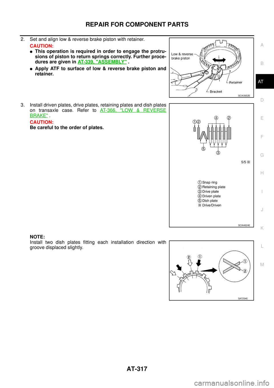
2. Set and align low & reverse brake piston with retainer.
CAUTION:
�This operation is required in order to engage the protru-
sions of piston to return springs correctly. Further proce-
dures are given in AT- 3 3 9 , "
ASSEMBLY" .
�Apply ATF to surface of low & reverse brake piston and
retainer.
3. Install driven plates, drive plates, retaining plates and dish plates
on transaxle case. Refer to AT- 3 6 6 , "
LOW & REVERSE
BRAKE" .
CAUTION:
Be careful to the order of plates.
NOTE:
Install two dish plates fitting each installation direction with
groove displaced slightly.
SCIA3652E
SCIA4624E
SAT254E
Page 326 of 3502
AT-318
REPAIR FOR COMPONENT PARTS
4. Install snap ring with flat-bladed screwdriver.
5. Measure clearance between retaining plate (1) and transaxle
case (2) with feeler gauge (3). If not within allowable limit, select
proper retaining plate (front side) (4). Refer to “Parts Informa-
tion” for retaining plate selection.
6. Install low & reverse brake piston (with retainer) and spring retainer on transaxle case.
7. Install snap ring with flat-bladed screwdriver.
8. Check operation of low & reverse brake. Refer to AT- 3 1 5 , "
DIS-
ASSEMBLY" .
SCIA4904E
Specified clearance
Standard and allowable limit:
Refer to AT- 3 6 6 , "
LOW & REVERSE BRAKE" .
SCIA7731E
SCIA4903E
 and seal lip (2) on reverse clutch piston (3).
CAUTION:
Be careful to direction of seal lip (2).
2. Install reverse clutch piston by")


 and transaxle
case (2) with feeler gauge (3). If not within allo")