Page 249 of 3502
TRANSAXLE ASSEMBLY
AT-241
D
E
F
G
H
I
J
K
L
MA
B
AT
TRANSAXLE ASSEMBLYPFP:32020
Removal and InstallationBCS0015B
COMPONENTS (FOR QR20DE ENGINE MODELS)
1. A/T fluid level gauge 2. O-ring 3. A/T fluid charging pipe
4. Front engine mounting bracket 5. Fluid cooler tube 6. Fluid cooler tube
7. Copper washer 8. Copper washer 9. A/T assembly
10. Stopper 11. LH engine mounting insulator 12. Rear engine mounting bracket
Refer to GI section to make sure icons (symbol marks) in the figure. Refer to GI-10, "
Components" .
However, refer to the following symbols for others.
: For tightening torque, refer to AT- 2 4 4 , "
INSTALLATION" .
SCIA7837E
Page 250 of 3502

AT-242
TRANSAXLE ASSEMBLY
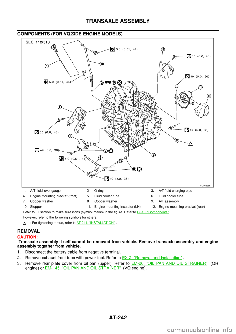
COMPONENTS (FOR VQ23DE ENGINE MODELS)
REMOVAL
CAUTION:
Transaxle assembly it self cannot be removed from vehicle. Remove transaxle assembly and engine
assembly together from vehicle.
1. Disconnect the battery cable from negative terminal.
2. Remove exhaust front tube with power tool. Refer to EX-2, "
Removal and Installation" .
3. Remove rear plate cover from oil pan (upper). Refer to EM-26, "
OIL PAN AND OIL STRAINER" (QR
engine) or EM-145, "
OIL PAN AND OIL STRAINER" (VQ engine).
1. A/T fluid level gauge 2. O-ring 3. A/T fluid charging pipe
4. Engine mounting bracket (front) 5. Fluid cooler tube 6. Fluid cooler tube
7. Copper washer 8. Copper washer 9. A/T assembly
10. Stopper 11. Engine mounting insulator (LH) 12. Engine mounting bracket (rear)
Refer to GI section to make sure icons (symbol marks) in the figure. Refer to GI-10, "
Components" .
However, refer to the following symbols for others.
: For tightening torque, refer to AT-244, "
INSTALLATION" .
SCIA7838E
Page 825 of 3502
BRAKE PEDAL
BR-7
C
D
E
G
H
I
J
K
L
MA
B
BR
Removal and InstallationBFS000BH
COMPONENTS
NOTE:
Clevis pin can be installed from both left and right.
REMOVAL
1. Remove instrument driver lower panel. Refer to IP-10,
"INSTRUMENT PANEL ASSEMBLY" .
2. Disconnect stop lamp switch connector, brake switch and/or
ASCD cancel switch connector.
3. Remove stop lamp switch, brake switch and/or ASCD cancel
switch from brake pedal assembly.
4. Remove snap pin and clevis pin from brake booster clevis.
5. Remove pedal bracket mounting nuts and bolt, and remove
brake pedal assembly from vehicle.
1. Clevis pin 2. Clip 3. Stop lamp switch
4. Brake switch (Models with VDC)
ASCD cancel switch (Models with
ASCD)5. Brake pedal pad 6. Brake pedal assembly
7. Snap pin
Refer to GI-10, "
Components" and the followings for the symbols in the figure.
: Apply multi-purpose grease.
PFIA0836E
SFIA2044E
Page 833 of 3502
BRAKE MASTER CYLINDER
BR-15
C
D
E
G
H
I
J
K
L
MA
B
BR
Disassembly and AssemblyBFS000BR
COMPONENTS
1. Reservoir tank 2. Reservoir cap 3. Oil strainer
(Models with VDC)
4. Pin 5. Cylinder body 6. Piston stopper
(Models with VDC)
7. Grommet 8. Secondary piston assembly 9. Primary piston assembly
10. O-ring 11. Snap ring 12. Guide assembly
13. Plate 14. Stopper cap
Refer to GI-10, "
Components" and the followings for the symbols in the figure.
: Apply PBC (Poly Butyl Cuprysil) grease or silicone-based grease.
: Apply brake fluid.
PFIA0822E
Page 844 of 3502

BR-26
FRONT DISC BRAKE
FRONT DISC BRAKEPFP:41000
On-Board InspectionBFS000BX
PAD WEAR INSPECTION
�Check pad thickness from the inspection hole on cylinder body.
Check use a scale for inspection necessary.
ComponentsBFS000BY
WARNING:
Clean dust on caliper and brake pads with a vacuum dust collector to minimize the hazard of airborne
particles or other materials.
CAUTION:
�While removing cylinder body, never depress brake pedal because piston will pop out. Standard thickness : 11.0 mm (0.433 in)
Repair limit thickness : 2.0 mm (0.079 in)
BRA0010D
1. Union bolt 2. Brake hose 3. Copper washer
4. Cap 5. Bleed valve 6. Sliding pin bolt
7. Cylinder body 8. Piston seal 9. Piston
10. Piston boot 11. Inner shim cover 12. Inner shim
13. Pad wear sensor
(Only for inner pad RH)14. Inner pad 15. Pad retainer
16. Outer pad 17. Outer shim 18. Sliding pin
19. Sliding pin boot 20. Bushing 21. Torque member
22. Torque member mounting bolt
Refer to GI-10, "
Components" and the followings for the symbols in the figure.
1: Apply rubber grease.
2: Apply PBC (Poly Butyl Cuprysil) grease or silicone-based grease.
3: Apply polyglycol ether based lubricant.
: Apply brake fluid.
PFIA0837E
Page 852 of 3502

BR-34
REAR DISC BRAKE
WARNING:
Clean dust on caliper and brake pads with a vacuum dust collector to minimize the hazard of air borne
particles or other materials.
CAUTION:
�While removing cylinder body, do never depress brake pedal because piston will pop out.
�It is not necessary to remove bolts on torque member and brake hose except for disassembly or
replacement of caliper assembly. In this case, hang cylinder body with wire so as not to stretch
brake hose.
�Do not damage piston boot.
�If any shim is subject to serious corrosion, replace it with a new one.
�Always replace shims and shim covers as a set when replacing brake pads.
�Keep rotor clean from brake fluid.
�Burnish brake contact surface after refinishing or replacing rotors, after replacing pads, or if a soft
pedal occurs at very low mileage. Refer to BR-39, "
BRAKE BURNISHING PROCEDURE" .
Removal and Installation of Brake PadBFS000C4
REMOVAL
1. Remove tyres from vehicle.
2. Remove upper sliding pin bolt.
3. Suspend cylinder body with wire, and remove pads, pad retainers and shims, and shim covers from
torque member.
INSTALLATION
1. Apply PBC (Poly Butyl Cuprysil) grease or silicone-based grease to the bosh side of inner shim and outer
shin, install inner shim, inner shim cover to inner pad, and outer shim, outer shim cover to outer pad.
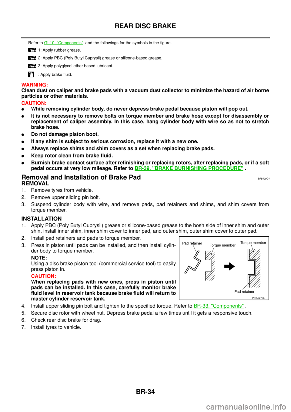
2. Install pad retainers and pads to torque member.
3. Press in piston until pads can be installed, and then install cylin-
der body to torque member.
NOTE:
Using a disc brake piston tool (commercial service tool) to easily
press piston in.
CAUTION:
When replacing pads with new ones, press in piston until
pads can be installed. In this case, carefully monitor brake
fluid level in reservoir tank because brake fluid will return to
master cylinder reservoir tank.
4. Install upper sliding pin bolt and tighten to the specified torque. Refer to BR-33, "
Components" .
5. Secure disc rotor with wheel nut. Depress brake pedal a few times until it gets a responsive touch.
6. Check rear disc brake for drag.
7. Install tyres to vehicle.
Refer to GI-10, "Components" and the followings for the symbols in the figure.
1: Apply rubber grease.
2: Apply PBC (Poly Butyl Cuprysil) grease or silicone-based grease.
3: Apply polyglycol ether based lubricant.
: Apply brake fluid.
PFIA0273E
Page 1193 of 3502
DIFFERENTIAL SIDE OIL SEAL
CVT-187
D
E
F
G
H
I
J
K
L
MA
B
CVT
DIFFERENTIAL SIDE OIL SEALPFP:33111
Removal and InstallationBCS001MW
COMPONENTS
REMOVAL
1. Remove drive shaft assembly. Refer to FA X - 8 , "FRONT DRIVE
SHAFT" .
2. Remove differential side oil seals using a flat-bladed screw-
driver.
CAUTION:
Be careful not to scratch transaxle case and converter
housing.
1. Transaxle assembly 2. Differential side oil seal
Refer to GI section to make sure icons (symbol marks) in the figure. Refer to GI-10, "
Components" .
However, refer to the following symbols for others.
: Apply CVT Fluid NS-2.
SCIA7917E
SCIA2412E
Page 1195 of 3502
CVT FLUID COOLER SYSTEM
CVT-189
D
E
F
G
H
I
J
K
L
MA
B
CVT
CVT FLUID COOLER SYSTEMPFP:21600
CVT Fluid Cooler Removal and InstallationBCS001MX
COMPONENTS
1. Harness bracket 2. CVT fluid cooler inlet tube assembly 3. Transaxle assembly
4. Hose clamp 5. Inlet water hose 6. Hose clamp
7. Outlet water hose 8. Heater hose 9. Hose clamp
10. CVT fluid cooler outlet tube assem-
bly11. CVT fluid cooler valve assembly
A. O-ring
Refer to GI section to make sure icons (symbol marks) in the figure. Refer to GI-10, "
Components" .
However, refer to the following symbols for others.
: Apply engine coolant or equivalent.
SCIA7740E