HYDRAULIC LINE
PS-39
C
D
E
F
H
I
J
K
L
MA
B
PS
HYDRAULIC LINEPFP:49721
Removal and InstallationBGS00041
COMPONENTS (EXCEPT FOR QR20DE MODELS)
1. Reservoir tank 2. Reservoir tank bracket 3. Suction hose
4. Oil pump assembly 5. High pressure hose 6. Steering gear assembly
7. Low pressure piping 8. High pressure piping 9. O-ring
10. Clamp 11. Copper washer 12. Eye-joint (assembled to high pres-
sure side hose)
13. Pressure sensor 14. Eye-bolt
Refer to GI-10, "
Components" , and the followings for the symbols in the figure.
: Apply power steering fluid.
SGIA1621E
PS-40
HYDRAULIC LINE
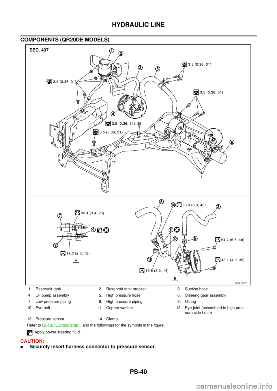
COMPONENTS (QR20DE MODELS)
CAUTION:
�Securely insert harness connector to pressure sensor.
1. Reservoir tank 2. Reservoir tank bracket 3. Suction hose
4. Oil pump assembly 5. High pressure hose 6. Steering gear assembly
7. Low pressure piping 8. High pressure piping 9. O-ring
10. Eye-bolt 11. Copper washer 12. Eye-joint (assembled to high pres-
sure side hose)
13. Pressure sensor 14. Clamp
Refer to GI-10, "
Components" , and the followings for the symbols in the figure.
: Apply power steering fluid.
SGIA1622E
RSU-8
REAR SUSPENSION ASSEMBLY
Removal and InstallationBES00043
REMOVAL
1. Remove tires from vehicle.
2. Remove wheel sensor from axle housing, and then disconnect sensor harness from suspension arm and
suspension member. Refer to BRC-33, "
WHEEL SENSORS" .
CAUTION:
Do not pull on wheel sensor harness.
3. Remove torque member fixing bolts. Hang torque member in a place where it will not interfere with work.
Refer to BR-33, "
REAR DISC BRAKE" .
NOTE:
Do not depress brake pedal while brake caliper is removed.
4. Remove main muffler and center muffler. Refer to EX-2, "
EXHAUST SYSTEM" .
5. Remove parking brake cable (rear cables) from rear suspension member and body. Refer to PB-3,
"PARKING BRAKE CONTROL" .
6. Remove coil spring. Refer to RSU-15, "
REAR LOWER LINK & COIL SPRING" .
7. Remove the mounting nuts on the upper side of shock absorber assembly. Refer to RSU-9, "
SHOCK
ABSORBER" .
8. Set jack under rear suspension member.
9. Remove rear suspension member mounting nuts, and then remove rebound stopper.
10. Gradually lower jack to remove rear suspension assembly.
INSTALLATION
�Installation is the reverse order of the removal. For tightening torque, refer to RSU-7, "Component" .
NOTE:
Do not reuse non-reusable parts.
�Perform final tightening of each parts under unladen conditions, which were removed when removing rear
suspension assembly. Check the wheel alignment. Refer to RSU-5, "
Wheel Alignment Inspection" .
�Adjust neutral position of steering angle sensor after checking the wheel alignment for models with VDC.
Refer to BRC-40, "
Adjustment of Steering Angle Sensor Neutral Position" .
�Check for the following after finishing work.
–Parking brake operation (stroke): Refer to PB-2, "On-Vehicle Inspection" .
–Wheel sensor harness for proper connection: Refer to BRC-33, "WHEEL SENSORS" .
1. Outer washer 2. Bushing (upper) 3. Distance tube
4. Mounting seal bracket 5. Bushing (lower) 6. Bound bumper cover
7. Bound bumper 8. Shock absorber 9. Upper seat
10. Coil spring 11. Rubber seat 12. Rear lower link
13. Axle housing assembly 14. Front lower link 15. Radius rod
16. Suspension arm 17. Connecting rod mounting bracket 18. Rebound stopper
19. Shock absorber assembly 20. Rear suspension member 21. Front lower link protector
22. Stabilizer bar 23. Connecting rod 24. Stabilizer bushing
25. Stabilizer clamp 26. Cotter pin 27. Washer
28. Ball seat
Refer to GI-10, "
Components" , for the symbols in the figure.

1. Reservoir tank 2. Reservoir tank bracket 3. Suction h")