2003 NISSAN TEANA cruise control
[x] Cancel search: cruise controlPage 1 of 3502
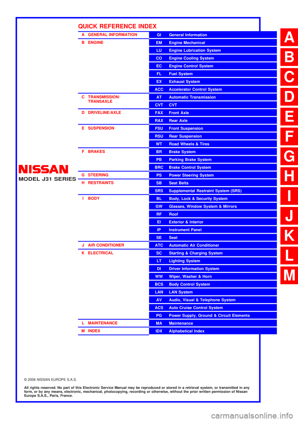
MODEL J31 SERIES
2006 NISSAN EUROPE S.A.S.
All rights reserved. No part of this Electronic Service Manual may be reproduced or stored in a retrieval system, or transmitted in any
form, or by any means, electronic, mechanical, photocopying, recording or otherwise, without the prior written permission of Nissan
Europe S.A.S., Paris, France.
A GENERAL INFORMATION
B ENGINE
C TRANSMISSION/TRANSAXLE
D DRIVELINE/AXLE
E SUSPENSION
F BRAKES
G STEERING H RESTRAINTS
I BODY
J AIR CONDITIONER
K ELECTRICAL
L MAINTENANCE
M INDEXGI General Information
EM Engine Mechanical
LU Engine Lubrication System
CO Engine Cooling System
EC Engine Control System
FL Fuel System
EX Exhaust System
ACC Accelerator Control System
AT Automatic Transmission
CVT CVT
FAX Front Axle
RAX Rear Axle
FSU Front Suspension
RSU Rear Suspension
WT Road Wheels & Tires
BR Brake System
PB Parking Brake System
BRC Brake Control System
PS Power Steering System
SB Seat Belts
SRS Supplemental Restraint System (SRS)
BL Body, Lock & Security System
GW Glasses, Window System & Mirrors
RF Roof
EI Exterior & Interior
IP Instrument Panel
SE Seat
ATC Automatic Air Conditioner
SC Starting & Charging System
LT Lighting System
DI Driver Information System
WW Wiper, Washer & Horn
BCS Body Control System
LAN LAN System
AV Audio, Visual & Telephone System
ACS Auto Cruise Control System
PG Power Supply, Ground & Circuit Elements
MA Maintenance
IDX Alphabetical Index
QUICK REFERENCE INDEX
A
B
C
D
E
F
G
H
I
J
K
L
M
Page 7 of 3502
ACS-1
AUTO CRUISE CONTROL SYSTEM
K ELECTRICAL
CONTENTS
C
D
E
F
G
H
I
J
L
M
SECTION ACS
A
B
ACS
AUTO CRUISE CONTROL SYSTEM
AUTOMATIC SPEED CONTROL DEVICE (ASCD) ..... 2
Description ............................................................... 2
Page 9 of 3502

AT-1
AUTOMATIC TRANSAXLE
C TRANSMISSION/TRANSAXLE
CONTENTS
D
E
F
G
H
I
J
K
L
M
SECTION AT
A
B
AT
AUTOMATIC TRANSAXLE
INDEX FOR DTC ........................................................ 5
Alphabetical Index .................................................... 5
PRECAUTIONS .......................................................... 6
Precautions for Supplemental Restraint System
(SRS) “AIR BAG” and “SEAT BELT PRE-TEN-
SIONER” .................................................................. 6
Precautions Necessary for Steering Wheel Rotation
After Battery Disconnect .......................................... 6
Precautions .............................................................. 7
Service Notice or Precautions .................................. 8
PREPARATION ........................................................... 9
Special Service Tools ............................................... 9
Commercial Service Tools ...................................... 12
A/T FLUID ................................................................. 14
Checking A/T Fluid ................................................. 14
Changing A/T Fluid ................................................ 15
A/T CONTROL SYSTEM .......................................... 16
Cross-Sectional View ............................................. 16
Shift Mechanism ..................................................... 17
TCM Function ......................................................... 26
CAN Communication .............................................. 27
Input/Output Signal of TCM .................................... 27
Line Pressure Control ............................................ 28
Shift Control ........................................................... 29
Lock-up Control ...................................................... 30
Engine Brake Control (Overrun Clutch Control) ..... 31
Control Valve .......................................................... 33
TROUBLE DIAGNOSIS ............................................ 34
DTC Inspection Priority Chart ................................ 34
Fail-safe ................................................................. 34
How to Perform Trouble Diagnoses for Quick and
Accurate Repair ..................................................... 36
A/T Electrical Parts Location .................................. 41
Circuit Diagram ...................................................... 42
Inspections Before Trouble Diagnosis .................... 43
Road Test ............................................................... 48
Check Before Engine Is Started ............................. 48
Check at Idle .......................................................... 48
Cruise Test — Part 1 .............................................. 50
Cruise Test — Part 2 .............................................. 51Cruise Test — Part 3 .............................................. 52
Vehicle Speed Which Gear Shifting Occurs ........... 54
Vehicle Speed at When Lock-up Occurs/Releases ... 54
Symptom Chart ....................................................... 55
TCM Terminals and Reference Value ..................... 64
CONSULT-II Function (A/T) .................................... 67
Diagnostic Procedure Without CONSULT-II ........... 76
VEHICLE SPEED SENSOR·A/T (REVOLUTION
SENSOR) .................................................................. 80
Description .............................................................. 80
CONSULT-II Reference Value ................................ 80
On Board Diagnosis Logic ...................................... 80
Possible Cause ....................................................... 80
DTC Confirmation Procedure ................................. 80
Wiring Diagram — AT — VSSA/T .......................... 82
Diagnostic Procedure ............................................. 83
VEHICLE SPEED SENSOR MTR ............................. 86
Description .............................................................. 86
CONSULT-II Reference Value ................................ 86
On Board Diagnosis Logic ...................................... 86
Possible Cause ....................................................... 86
DTC Confirmation Procedure ................................. 86
Wiring Diagram — AT — VSSMTR ........................ 87
Diagnostic Procedure ............................................. 88
SHIFT SOLENOID VALVE A .................................... 90
Description .............................................................. 90
CONSULT-II Reference Value ................................ 90
On Board Diagnosis Logic ...................................... 90
Possible Cause ....................................................... 90
DTC Confirmation Procedure ................................. 90
Wiring Diagram — AT — SSV/A ............................. 91
Diagnostic Procedure ............................................. 92
Component Inspection ............................................ 94
SHIFT SOLENOID VALVE B .................................... 95
Description .............................................................. 95
CONSULT-II Reference Value ................................ 95
On Board Diagnosis Logic ...................................... 95
Possible Cause ....................................................... 95
DTC Confirmation Procedure ................................. 95
Wiring Diagram — AT — SSV/B ............................. 96
Page 48 of 3502
AT-40
TROUBLE DIAGNOSIS
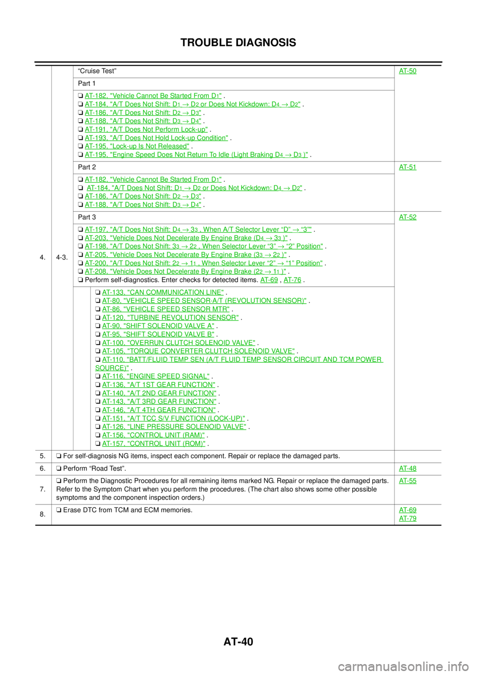
4. 4-3.“Cruise Test”AT- 5 0
Part 1
❏ AT-182, "
Vehicle Cannot Be Started From D1" .
❏ AT-184, "
A/T Does Not Shift: D1 → D2 or Does Not Kickdown: D4 → D2" .
❏ AT-186, "
A/T Does Not Shift: D2 → D3" .
❏ AT-188, "
A/T Does Not Shift: D3 → D4" .
❏ AT-191, "
A/T Does Not Perform Lock-up" .
❏ AT-193, "
A/T Does Not Hold Lock-up Condition" .
❏ AT-195, "
Lock-up Is Not Released" .
❏ AT-195, "
Engine Speed Does Not Return To Idle (Light Braking D4 → D3 )" .
Part 2AT- 5 1
❏ AT-182, "Vehicle Cannot Be Started From D1" .
❏ AT- 1 8 4 , "
A/T Does Not Shift: D1 → D2 or Does Not Kickdown: D4 → D2" .
❏ AT-186, "
A/T Does Not Shift: D2 → D3" .
❏ AT-188, "
A/T Does Not Shift: D3 → D4" .
Part 3AT- 5 2
❏ AT-197, "A/T Does Not Shift: D4 → 33 , When A/T Selector Lever “D” → “3”" .
❏ AT-203, "
Vehicle Does Not Decelerate By Engine Brake (D4 → 33 )" .
❏ AT-198, "
A/T Does Not Shift: 33 → 22 , When Selector Lever “3” → “2” Position" .
❏ AT-205, "
Vehicle Does Not Decelerate By Engine Brake (33 → 22 )" .
❏ AT-200, "
A/T Does Not Shift: 22 → 11 , When Selector Lever “2” → “1” Position" .
❏ AT-208, "
Vehicle Does Not Decelerate By Engine Brake (22 → 11 )" .
❏ Perform self-diagnostics. Enter checks for detected items. AT- 6 9
, AT- 7 6 .
❏ AT-133, "
CAN COMMUNICATION LINE" .
❏ AT-80, "
VEHICLE SPEED SENSOR·A/T (REVOLUTION SENSOR)" .
❏ AT-86, "
VEHICLE SPEED SENSOR MTR" .
❏ AT-120, "
TURBINE REVOLUTION SENSOR" .
❏ AT-90, "
SHIFT SOLENOID VALVE A" .
❏ AT-95, "
SHIFT SOLENOID VALVE B" .
❏ AT-100, "
OVERRUN CLUTCH SOLENOID VALVE" .
❏ AT-105, "
TORQUE CONVERTER CLUTCH SOLENOID VALVE" .
❏ AT-110, "
BATT/FLUID TEMP SEN (A/T FLUID TEMP SENSOR CIRCUIT AND TCM POWER
SOURCE)" .
❏ AT-116, "
ENGINE SPEED SIGNAL" .
❏ AT-136, "
A/T 1ST GEAR FUNCTION" .
❏ AT-140, "
A/T 2ND GEAR FUNCTION" .
❏ AT-143, "
A/T 3RD GEAR FUNCTION" .
❏ AT-146, "
A/T 4TH GEAR FUNCTION" .
❏ AT-151, "
A/T TCC S/V FUNCTION (LOCK-UP)" .
❏ AT-126, "
LINE PRESSURE SOLENOID VALVE" .
❏ AT-156, "
CONTROL UNIT (RAM)" .
❏ AT-157, "
CONTROL UNIT (ROM)" .
5.❏ For self-diagnosis NG items, inspect each component. Repair or replace the damaged parts.
6.❏ Perform “Road Test”.AT- 4 8
7.❏ Perform the Diagnostic Procedures for all remaining items marked NG. Repair or replace the damaged parts.
Refer to the Symptom Chart when you perform the procedures. (The chart also shows some other possible
symptoms and the component inspection orders.)AT- 5 5
8.❏ Erase DTC from TCM and ECM memories.AT- 6 9AT- 7 9
Page 79 of 3502
TROUBLE DIAGNOSIS
AT-71
D
E
F
G
H
I
J
K
L
MA
B
AT
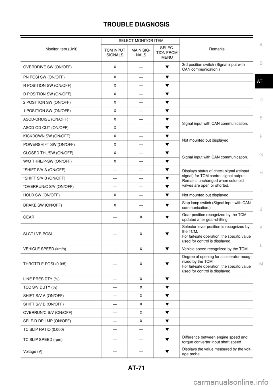
OVERDRIVE SW (ON/OFF) X —3rd position switch (Signal input with
CAN communication.)
PN POSI SW (ON/OFF) X —
R POSITION SW (ON/OFF) X —
D POSITION SW (ON/OFF) X —
2 POSITION SW (ON/OFF) X —
1 POSITION SW (ON/OFF) X —
ASCD-CRUISE (ON/OFF) X —
Signal input with CAN communication.
ASCD-OD CUT (ON/OFF) X —
KICKDOWN SW (ON/OFF) X —
Not mounted but displayed.
POWERSHIFT SW (ON/OFF) X —
CLOSED THL/SW (ON/OFF) X —
Signal input with CAN communication.
W/O THRL/P-SW (ON/OFF) X —
*SHIFT S/V A (ON/OFF) — —
Displays status of check signal (reinput
signal) for TCM control signal output.
Remains unchanged when solenoid
valves are open or shorted. *SHIFT S/V B (ON/OFF) — —
*OVERRUN/C S/V (ON/OFF) — —
HOLD SW (ON/OFF) X — Not mounted but displayed.
BRAKE SW (ON/OFF) X —Stop lamp switch (Signal input with CAN
communication.)
GEAR — XGear position recognized by the TCM
updated after gear-shifting
SLCT LVR POSI — XSelector lever position is recognized by
the TCM.
For fail-safe operation, the specific value
used for control is displayed.
VEHICLE SPEED (km/h) — X Vehicle speed recognized by the TCM.
THROTTLE POSI (0.0/8) — XDegree of opening for accelerator recog-
nized by the TCM
For fail-safe operation, the specific value
used for control is displayed.
LINE PRES DTY (%) — X
TCC S/V DUTY (%) — X
SHIFT S/V A (ON/OFF) — X
SHIFT S/V B (ON/OFF) — X
OVERRUN/C S/V (ON/OFF) — X
SELF-D DP LMP (ON/OFF) — X
TC SLIP RATIO (0.000) — —
TC SLIP SPEED (rpm) — —Difference between engine speed and
torque converter input shaft speed
Voltage (V) — —Displays the value measured by the volt-
age probe. Monitor item (Unit)SELECT MONITOR ITEM
Remarks
TCM INPUT
SIGNALSMAIN SIG-
NALSSELEC-
TION FROM
MENU
Page 157 of 3502
A/T 4TH GEAR FUNCTION
AT-149
D
E
F
G
H
I
J
K
L
MA
B
AT
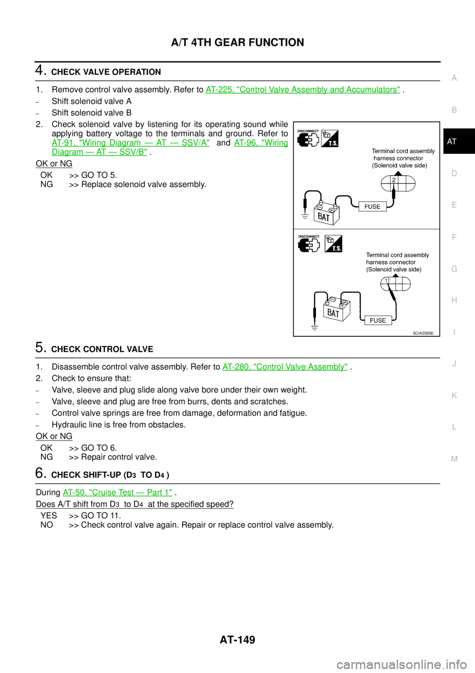
4. CHECK VALVE OPERATION
1. Remove control valve assembly. Refer to AT- 2 2 5 , "
Control Valve Assembly and Accumulators" .
–Shift solenoid valve A
–Shift solenoid valve B
2. Check solenoid valve by listening for its operating sound while
applying battery voltage to the terminals and ground. Refer to
AT- 9 1 , "
Wiring Diagram — AT — SSV/A" and AT- 9 6 , "Wiring
Diagram — AT — SSV/B" .
OK or NG
OK >> GO TO 5.
NG >> Replace solenoid valve assembly.
5. CHECK CONTROL VALVE
1. Disassemble control valve assembly. Refer to AT- 2 8 0 , "
Control Valve Assembly" .
2. Check to ensure that:
–Valve, sleeve and plug slide along valve bore under their own weight.
–Valve, sleeve and plug are free from burrs, dents and scratches.
–Control valve springs are free from damage, deformation and fatigue.
–Hydraulic line is free from obstacles.
OK or NG
OK >> GO TO 6.
NG >> Repair control valve.
6. CHECK SHIFT-UP (D3 TO D4 )
During AT- 5 0 , "
Cruise Test — Part 1" .
Does A/T shift from D
3 to D4 at the specified speed?
YES >> GO TO 11.
NO >> Check control valve again. Repair or replace control valve assembly.
SCIA3595E
Page 158 of 3502
AT-150
A/T 4TH GEAR FUNCTION
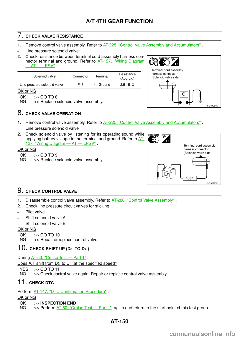
7. CHECK VALVE RESISTANCE
1. Remove control valve assembly. Refer to AT- 2 2 5 , "
Control Valve Assembly and Accumulators" .
–Line pressure solenoid valve
2. Check resistance between terminal cord assembly harness con-
nector terminal and ground. Refer to AT- 1 2 7 , "
Wiring Diagram
— AT — LPSV" .
OK or NG
OK >> GO TO 8.
NG >> Replace solenoid valve assembly.
8. CHECK VALVE OPERATION
1. Remove control valve assembly. Refer to AT- 2 2 5 , "
Control Valve Assembly and Accumulators" .
–Line pressure solenoid valve
2. Check solenoid valve by listening for its operating sound while
applying battery voltage to the terminal and ground. Refer to AT-
127, "Wiring Diagram — AT — LPSV" .
OK or NG
OK >> GO TO 9.
NG >> Replace solenoid valve assembly.
9. CHECK CONTROL VALVE
1. Disassemble control valve assembly. Refer to AT- 2 8 0 , "
Control Valve Assembly" .
2. Check line pressure circuit valves for sticking.
–Pilot valve
–Shift solenoid valve A
–Shift solenoid valve B
OK or NG
OK >> GO TO 10.
NG >> Repair or replace control valve.
10. CHECK SHIFT-UP (D3 TO D4 )
During AT- 5 0 , "
Cruise Test — Part 1" .
Does A/T shift from D
3 to D4 at the specified speed?
YES >> GO TO 11.
NO >> Check control valve again. Repair or replace control valve assembly.
11 . CHECK DTC
Perform AT- 1 4 7 , "
DTC Confirmation Procedure" .
OK or NG
OK >>INSPECTION END
NG >> Perform AT- 5 0 , "
Cruise Test — Part 1" again and return to the start point of this test group.
Solenoid valve Connector TerminalResistance
(Approx.)
Line pressure solenoid valve F43 4 - Ground 2.5 - 5Ω
SCIA4951E
SCIA3275E
Page 161 of 3502
A/T TCC S/V FUNCTION (LOCK-UP)
AT-153
D
E
F
G
H
I
J
K
L
MA
B
AT
3. CHECK CONTROL VALVE
1. Disassemble control valve assembly. Refer to AT- 2 8 0 , "
Control Valve Assembly" .
2. Check to ensure that:
–Valve, sleeve and plug slide along valve bore under their own weight.
–Valve, sleeve and plug are free from burrs, dents and scratches.
–Control valve springs are free from damage, deformation and fatigue.
–Hydraulic line is free from obstacles.
OK or NG
OK >> GO TO 4.
NG >> Repair or replace control valve.
4. CHECK SHIFT-UP (D3 TO D4 )
During AT- 5 0 , "
Cruise Test — Part 1" .
Does A/T shift from D
3 to D4 at the specified speed?
YES >> GO TO 5.
NO >> Check control valve again. Repair or replace control valve assembly.
5. CHECK DTC
Perform AT- 1 5 2 , "
DTC Confirmation Procedure" .
OK or NG
OK >>INSPECTION END
NG >> GO TO 11. Check for proper lock-up.
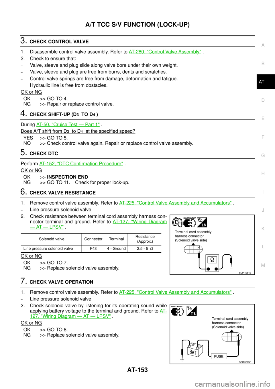
6. CHECK VALVE RESISTANCE
1. Remove control valve assembly. Refer to AT- 2 2 5 , "
Control Valve Assembly and Accumulators" .
–Line pressure solenoid valve
2. Check resistance between terminal cord assembly harness con-
nector terminal and ground. Refer to AT- 1 2 7 , "
Wiring Diagram
— AT — LPSV" .
OK or NG
OK >> GO TO 7.
NG >> Replace solenoid valve assembly.
7. CHECK VALVE OPERATION
1. Remove control valve assembly. Refer to AT- 2 2 5 , "
Control Valve Assembly and Accumulators" .
–Line pressure solenoid valve
2. Check solenoid valve by listening for its operating sound while
applying battery voltage to the terminal and ground. Refer to AT-
127, "Wiring Diagram — AT — LPSV" .
OK or NG
OK >> GO TO 8.
NG >> Replace solenoid valve assembly.
Solenoid valve Connector TerminalResistance
(Approx.)
Line pressure solenoid valve F43 4 - Ground 2.5 - 5Ω
SCIA4951E
SCIA3275E