2003 NISSAN TEANA Park light bulb
[x] Cancel search: Park light bulbPage 2689 of 3502
LT-1
LIGHTING SYSTEM
K ELECTRICAL
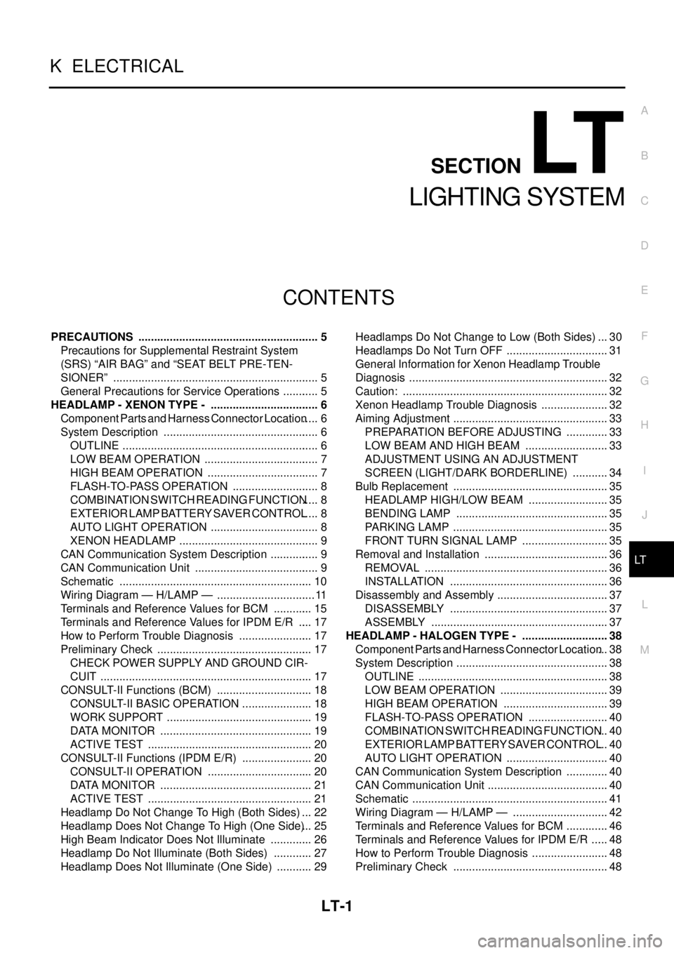
CONTENTS
C
D
E
F
G
H
I
J
L
M
SECTION LT
A
B
LT
LIGHTING SYSTEM
PRECAUTIONS .......................................................... 5
Precautions for Supplemental Restraint System
(SRS) “AIR BAG” and “SEAT BELT PRE-TEN-
SIONER” .................................................................. 5
General Precautions for Service Operations ............ 5
HEADLAMP - XENON TYPE - ................................... 6
Component Parts and Harness Connector Location ..... 6
System Description .................................................. 6
OUTLINE ............................................................... 6
LOW BEAM OPERATION ..................................... 7
HIGH BEAM OPERATION .................................... 7
FLASH-TO-PASS OPERATION ............................ 8
COMBINATION SWITCH READING FUNCTION ..... 8
EXTERIOR LAMP BATTERY SAVER CONTROL ..... 8
AUTO LIGHT OPERATION ................................... 8
XENON HEADLAMP ............................................. 9
CAN Communication System Description ................ 9
CAN Communication Unit ........................................ 9
Schematic .............................................................. 10
Wiring Diagram — H/LAMP — ................................ 11
Terminals and Reference Values for BCM ............. 15
Terminals and Reference Values for IPDM E/R ..... 17
How to Perform Trouble Diagnosis ........................ 17
Preliminary Check .................................................. 17
CHECK POWER SUPPLY AND GROUND CIR-
CUIT .................................................................... 17
CONSULT-II Functions (BCM) ............................... 18
CONSULT-II BASIC OPERATION ....................... 18
WORK SUPPORT ............................................... 19
DATA MONITOR ................................................. 19
ACTIVE TEST ..................................................... 20
CONSULT-II Functions (IPDM E/R) ....................... 20
CONSULT-II OPERATION .................................. 20
DATA MONITOR ................................................. 21
ACTIVE TEST ..................................................... 21
Headlamp Do Not Change To High (Both Sides) ... 22
Headlamp Does Not Change To High (One Side) ... 25
High Beam Indicator Does Not Illuminate .............. 26
Headlamp Do Not Illuminate (Both Sides) ............. 27
Headlamp Does Not Illuminate (One Side) ............ 29Headlamps Do Not Change to Low (Both Sides) ... 30
Headlamps Do Not Turn OFF ................................. 31
General Information for Xenon Headlamp Trouble
Diagnosis ................................................................ 32
Caution: .................................................................. 32
Xenon Headlamp Trouble Diagnosis ...................... 32
Aiming Adjustment .................................................. 33
PREPARATION BEFORE ADJUSTING .............. 33
LOW BEAM AND HIGH BEAM ........................... 33
ADJUSTMENT USING AN ADJUSTMENT
SCREEN (LIGHT/DARK BORDERLINE) ............ 34
Bulb Replacement .................................................. 35
HEADLAMP HIGH/LOW BEAM .......................... 35
BENDING LAMP ................................................. 35
PARKING LAMP .................................................. 35
FRONT TURN SIGNAL LAMP ............................ 35
Removal and Installation ........................................ 36
REMOVAL ........................................................... 36
INSTALLATION ................................................... 36
Disassembly and Assembly .................................... 37
DISASSEMBLY ................................................... 37
ASSEMBLY ......................................................... 37
HEADLAMP - HALOGEN TYPE - ............................ 38
Component Parts and Harness Connector Location ... 38
System Description ................................................. 38
OUTLINE ............................................................. 38
LOW BEAM OPERATION ................................... 39
HIGH BEAM OPERATION .................................. 39
FLASH-TO-PASS OPERATION .......................... 40
COMBINATION SWITCH READING FUNCTION ... 40
EXTERIOR LAMP BATTERY SAVER CONTROL ... 40
AUTO LIGHT OPERATION ................................. 40
CAN Communication System Description .............. 40
CAN Communication Unit ....................................... 40
Schematic ............................................................... 41
Wiring Diagram — H/LAMP — ............................... 42
Terminals and Reference Values for BCM .............. 46
Terminals and Reference Values for IPDM E/R ...... 48
How to Perform Trouble Diagnosis ......................... 48
Preliminary Check .................................................. 48
Page 2690 of 3502

LT-2 CHECK POWER SUPPLY AND GROUND CIR-
CUIT .................................................................... 48
CONSULT-II Functions (BCM) ................................ 49
CONSULT-II Functions (IPDM E/R) ........................ 49
Headlamp High Do Not Illuminate (Both Sides) ...... 50
Headlamp High Does Not Illuminate (One Side) .... 53
High Beam Indicator Does Not Illuminate ............... 54
Headlamp Low Beam Does Not Illuminate (Both
Sides) ..................................................................... 54
Headlamp Low Beam Does Not Illuminate (One
Side) ....................................................................... 57
Headlamps High Do Not Go OFF (Both Sides) ...... 58
Headlamps Low Do Not Go OFF (Both Sides) ....... 59
Aiming Adjustment .................................................. 60
PREPARATION BEFORE ADJUSTING .............. 60
LOW BEAM AND HIGH BEAM ........................... 60
ADJUSTMENT USING AN ADJUSTMENT
SCREEN (LIGHT/DARK BORDERLINE) ............ 61
Bulb Replacement .................................................. 62
HEADLAMP (UPPER) HIGH BEAM .................... 62
HEADLAMP (LOWER) LOW BEAM .................... 62
PARKING LAMP .................................................. 62
FRONT TURN SIGNAL LAMP ............................ 62
Removal and Installation ........................................ 62
Disassembly and Assembly .................................... 63
DISASSEMBLY ................................................... 63
ASSEMBLY ......................................................... 63
AUTO LIGHT SYSTEM ............................................. 64
Component Parts and Harness Connector Location ... 64
System Description ................................................. 64
OUTLINE ............................................................. 64
AUTO LIGHT OPERATION ................................. 65
COMBINATION SWITCH READING FUNCTION ... 65
HEADLAMP LOW AND HIGH OPERATION
(XENON TYPE) ................................................... 65
HEADLAMP LOW AND HIGH OPERATION
(HALOGEN TYPE) .............................................. 65
FRONT FOG LAMP OPERATION ....................... 65
PARKING, LICENSE PLATE AND TAIL LAMPS
OPERATION ........................................................ 65
CAN Communication System Description .............. 65
CAN Communication Unit ....................................... 65
Major Components and Functions .......................... 65
Wiring Diagram — AUTO/L — ................................ 66
Terminals and Reference Values for BCM .............. 68
Terminals and Reference Values for IPDM E/R ...... 69
How to Perform Trouble Diagnosis ......................... 69
Preliminary Check .................................................. 70
SETTING CHANGE FUNCTIONS ....................... 70
CHECK POWER SUPPLY AND GROUND CIR-
CUIT .................................................................... 70
CONSULT-II Functions (BCM) ................................ 71
Auto Light Function Does Not Operate ................... 71
Removal and Installation for Optical Sensor ........... 74
REMOVAL ........................................................... 74
INSTALLATION .................................................... 74
ACTIVE AFS ............................................................. 75
Component Parts and Harness Connector Location ... 75
System Description ................................................. 75AFS (ADAPTIVE FRONT-LIGHTING SYSTEM) ... 75
OUTLINE ............................................................. 76
BENDING LAMP OPERATION ............................ 76
CAN Communication System Description .............. 77
CAN Communication Unit ....................................... 77
Schematic ............................................................... 78
Wiring Diagram — AFS — ...................................... 79
Terminals and Reference Values for AFS Control
Unit .......................................................................... 82
CONSULT-II Functions (ADAPTIVE LIGHT) ........... 82
CONSULT-II BASIC OPERATION ....................... 82
WORK SUPPORT ............................................... 82
SELF-DIAG RESULTS ......................................... 84
DATA MONITOR .................................................. 86
ACTIVE TEST ...................................................... 87
AFS Operation Check (Function Test) .................... 88
Bending Lamps Do Not Illuminate (Both Side) ....... 90
Bending Lamp Does Not Illuminate (One Side) ...... 91
Bending Lamp Does Not turn OFF ......................... 92
DTC B2515 [ST ANG SEN SIG] ............................. 92
DTC B2516 [SHIFT POS SIG (P, R)] ...................... 93
DTC B2517 [VEHICLE SPEED SIG] ...................... 93
Aiming Adjustment .................................................. 94
Bulb Replacement ................................................... 94
Removal and Installation of AFS Control Unit ......... 94
REMOVAL ............................................................ 94
INSTALLATION .................................................... 94
Removal and Installation of Steering Angle Sensor ... 94
REMOVAL ............................................................ 94
INSTALLATION .................................................... 94
HEADLAMP AIMING CONTROL (AUTO) ................ 95
Component Parts and Harness connector Location ... 95
System Description ................................................. 96
OUTLINE ............................................................. 96
HEADLAMP AUTO AIMING CONTROL OPER-
ATION .................................................................. 97
CAN Communication System Description .............. 97
CAN Communication Unit ....................................... 97
Schematic ............................................................... 98
Wiring Diagram — H/AIM — ................................... 99
Terminals and Reference Values for Height Sensor .103
How to Proceed With Trouble Diagnosis ..............103
CONSULT-II Functions (HEADLAMP LEVELIZER) .103
CONSULT-II BASIC OPERATION .....................103
WORK SUPPORT .............................................103
DATA MONITOR ................................................104
ACTIVE TEST ....................................................105
SELF-DIAG RESULTS .......................................105
Check Aiming Control System ..............................107
Headlamp Aiming Motor Does Not Operate (Both
Sides) ....................................................................108
Headlamp Aiming Motor Does Not Operate (One
Side) ...................................................................... 111
DTC B2081 [INITIAL NOT DONE] ........................112
DTC B2082 [SENSOR OUT OF RANGE] .............112
DTC B2083 [SEN SIG NOT PLAUSIBLE] ............113
DTC B2084 [VOLTAGE UNDER LIMIT] ................113
DTC B2085 [LOW BEAM SIG OPEN LINE] .........114
DTC B2086 [FRQ. OVER LIMIT] ..........................115
Page 2692 of 3502

LT-4 Wiring Diagram — STOP/L — ..............................190
WITH REAR SUNSHADE AND REAR VIEW
CAMERA ...........................................................190
WITHOUT REAR SUNSHADE AND REAR VIEW
CAMERA ...........................................................191
Bulb Replacement ................................................192
HIGH-MOUNTED STOP LAMP .........................192
STOP LAMP ......................................................192
Removal and Installation ......................................192
HIGH-MOUNTED STOP LAMP .........................192
STOP LAMP ......................................................192
BACK-UP LAMP .....................................................193
Wiring Diagram — BACK/L — ..............................193
WITH A/T ...........................................................193
WITH CVT .........................................................194
Bulb Replacement ................................................195
Removal and Installation ......................................195
PARKING, LICENSE PLATE AND TAIL LAMPS ....196
Component Parts and Harness Connector Location .196
System Description ...............................................196
OUTLINE ...........................................................196
PARKING, LICENCE PLATE AND TAIL LAMPS
OPERATION ......................................................197
COMBINATION SWITCH READING FUNCTION .197
EXTERIOR LAMP BATTERY SAVER CONTROL .197
CAN Communication System Description ............198
CAN Communication Unit .....................................198
Schematic .............................................................199
Wiring Diagram — TAIL/L — ................................200
Terminals and Reference Values for BCM ............205
Terminals and Reference Values for IPDM E/R ....206
How to Perform Trouble Diagnoses ......................206
Preliminary Check ................................................206
CHECK POWER SUPPLY AND GROUND CIR-
CUIT ..................................................................206
CONSULT-II Functions (BCM) ..............................207
CONSULT-II Functions (IPDM E/R) ......................207
Parking, License Plate and Tail Lamps Do Not Illu-
minate ...................................................................208
Tail lamp Indicator Does Not Illuminate ................212
Parking, License Plate and Tail Lamps Do Not Go
OFF ......................................................................213
Bulb Replacement ................................................215
LICENSE PLATE LAMP ....................................215
PARKING LAMP ................................................215
TAIL LAMP ........................................................215
Removal and Installation ......................................215
LICENSE PLATE LAMP ....................................215
PARKING LAMP ................................................215
TAIL LAMP ........................................................215
REAR COMBINATION LAMP .................................216
Bulb Replacement ................................................216
REAR TURN SIGNAL LAMP BULB, BACK-UP
LAMP BULB AND STOP/TAIL LAMP BULB ......216
Removal and Installation ......................................216
REMOVAL .........................................................216
INSTALLATION ..................................................216
INTERIOR LAMP ....................................................217Wiring Diagram — INT/L — ..................................217
Bulb Replacement .................................................218
VANITY MIRROR LAMP ....................................218
INTERIOR ROOM LAMP ........................................219
Component Parts and Harness Connector Location .219
System Description ...............................................219
OUTLINE ...........................................................219
SWITCH OPERATION .......................................220
STEP LAMP OPERATION .................................221
TRUNK ROOM LAMP OPERATION ..................221
INTERIOR ROOM LAMP TIMER OPERATION .221
INTERIOR ROOM LAMP BATTERY SAVER
CONTROL .........................................................222
Schematic .............................................................223
Wiring Diagram — ROOM/L — .............................225
Terminals and Reference Values for BCM ............230
How to Perform With Trouble Diagnoses ..............231
Preliminary Check .................................................232
CHECK POWER SUPPLY AND GROUND CIR-
CUIT ...................................................................232
CONSULT-II Functions (BCM) ..............................233
CONSULT-II BASIC OPERATION .....................233
WORK SUPPORT (INT LAMP) .........................233
DATA MONITOR (INT LAMP) ............................233
ACTIVE TEST ....................................................234
WORK SUPPORT (BATTERY SAVER) .............234
DATA MONITOR (BATTERY SAVER) ...............235
Interior Room Lamps Do Not Illuminate ................236
Interior Room Lamps Illuminate But Timer Does Not
Operate .................................................................240
Bulb Replacement .................................................241
MAP LAMP ........................................................241
STEP LAMP .......................................................241
PERSONAL LAMP .............................................241
TRUNK ROOM LAMP ........................................241
IGNITION KEYHOLE ILLUMINATION ...............242
Removal and Installation .......................................242
MAP LAMP ........................................................242
STEP LAMP .......................................................242
PERSONAL LAMP .............................................243
TRUNK ROOM LAMP ........................................243
ILLUMINATION ........................................................244
System Description ...............................................244
OUTLINE ...........................................................244
ILLUMINATION OPERATION BY LIGHTING
SWITCH .............................................................244
EXTERIOR LAMP BATTERY SAVER CONTROL .246
CAN Communication System Description ............246
CAN Communication Unit .....................................246
Schematic .............................................................247
Wiring Diagram — ILL — ......................................249
Bulb Replacement .................................................260
ASHTRAY ILLUMINATION ................................260
GLOVE BOX LAMP ...........................................260
CIGARETTE LIGHTER ILLUMINATION ............260
BULB SPECIFICATIONS ........................................261
Headlamp ..............................................................261
Exterior Lamp ........................................................261
Interior Lamp/Illumination ......................................261
Page 2709 of 3502
HEADLAMP - XENON TYPE -
LT-21
C
D
E
F
G
H
I
J
L
MA
B
LT
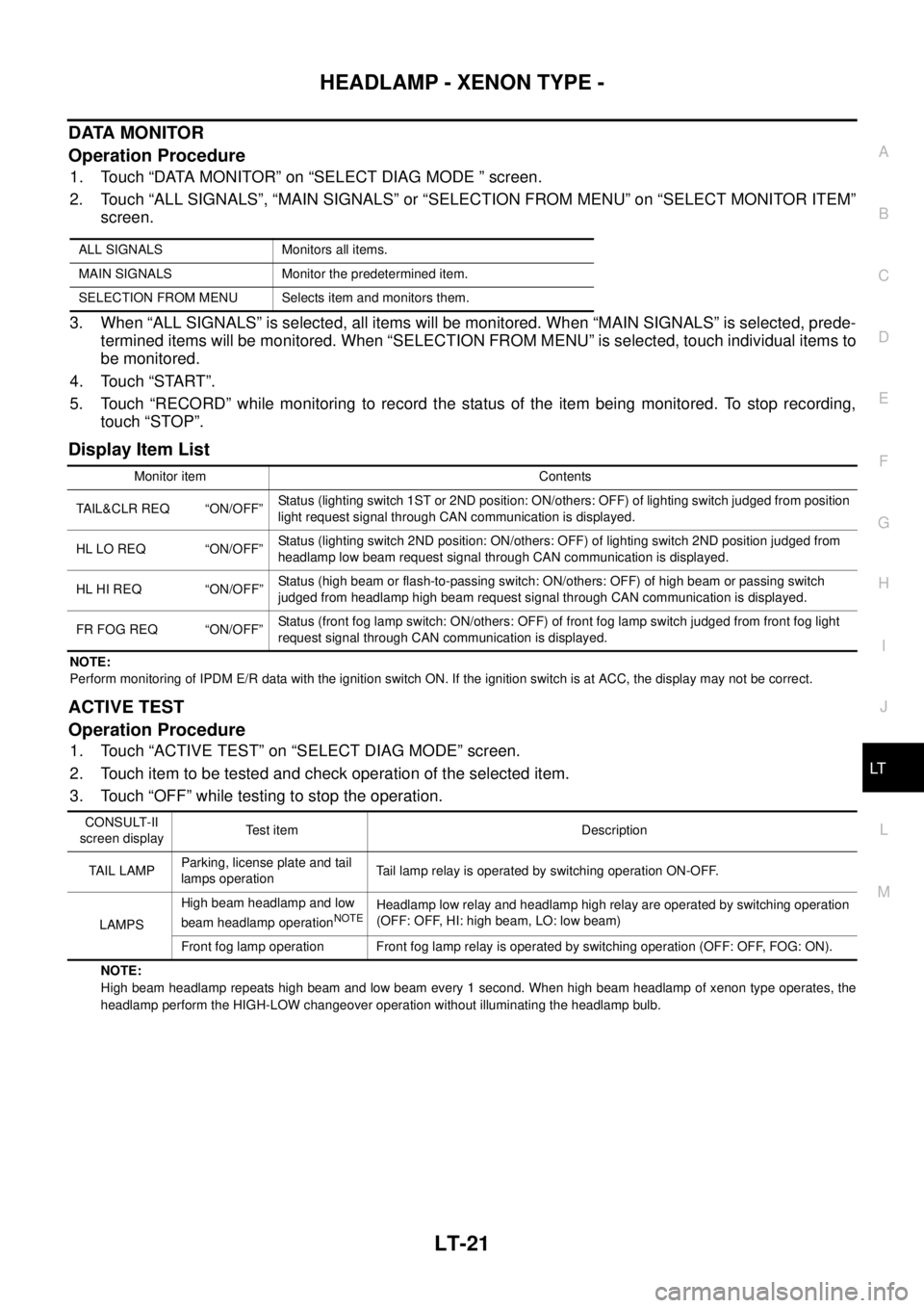
DATA MONITOR
Operation Procedure
1. Touch “DATA MONITOR” on “SELECT DIAG MODE ” screen.
2. Touch “ALL SIGNALS”, “MAIN SIGNALS” or “SELECTION FROM MENU” on “SELECT MONITOR ITEM”
screen.
3. When “ALL SIGNALS” is selected, all items will be monitored. When “MAIN SIGNALS” is selected, prede-
termined items will be monitored. When “SELECTION FROM MENU” is selected, touch individual items to
be monitored.
4. Touch “START”.
5. Touch “RECORD” while monitoring to record the status of the item being monitored. To stop recording,
touch “STOP”.
Display Item List
NOTE:
Perform monitoring of IPDM E/R data with the ignition switch ON. If the ignition switch is at ACC, the display may not be correct.
ACTIVE TEST
Operation Procedure
1. Touch “ACTIVE TEST” on “SELECT DIAG MODE” screen.
2. Touch item to be tested and check operation of the selected item.
3. Touch “OFF” while testing to stop the operation.
NOTE:
High beam headlamp repeats high beam and low beam every 1 second. When high beam headlamp of xenon type operates, the
headlamp perform the HIGH-LOW changeover operation without illuminating the headlamp bulb. ALL SIGNALS Monitors all items.
MAIN SIGNALS Monitor the predetermined item.
SELECTION FROM MENU Selects item and monitors them.
Monitor item Contents
TAIL&CLR REQ “ON/OFF”Status (lighting switch 1ST or 2ND position: ON/others: OFF) of lighting switch judged from position
light request signal through CAN communication is displayed.
HL LO REQ “ON/OFF”Status (lighting switch 2ND position: ON/others: OFF) of lighting switch 2ND position judged from
headlamp low beam request signal through CAN communication is displayed.
HL HI REQ “ON/OFF”Status (high beam or flash-to-passing switch: ON/others: OFF) of high beam or passing switch
judged from headlamp high beam request signal through CAN communication is displayed.
FR FOG REQ “ON/OFF”Status (front fog lamp switch: ON/others: OFF) of front fog lamp switch judged from front fog light
request signal through CAN communication is displayed.
CONSULT-II
screen displayTest item Description
TAIL LAMPParking, license plate and tail
lamps operationTail lamp relay is operated by switching operation ON-OFF.
LAMPSHigh beam headlamp and low
beam headlamp operation
NOTEHeadlamp low relay and headlamp high relay are operated by switching operation
(OFF: OFF, HI: high beam, LO: low beam)
Front fog lamp operation Front fog lamp relay is operated by switching operation (OFF: OFF, FOG: ON).
Page 2723 of 3502
HEADLAMP - XENON TYPE -
LT-35
C
D
E
F
G
H
I
J
L
MA
B
LT
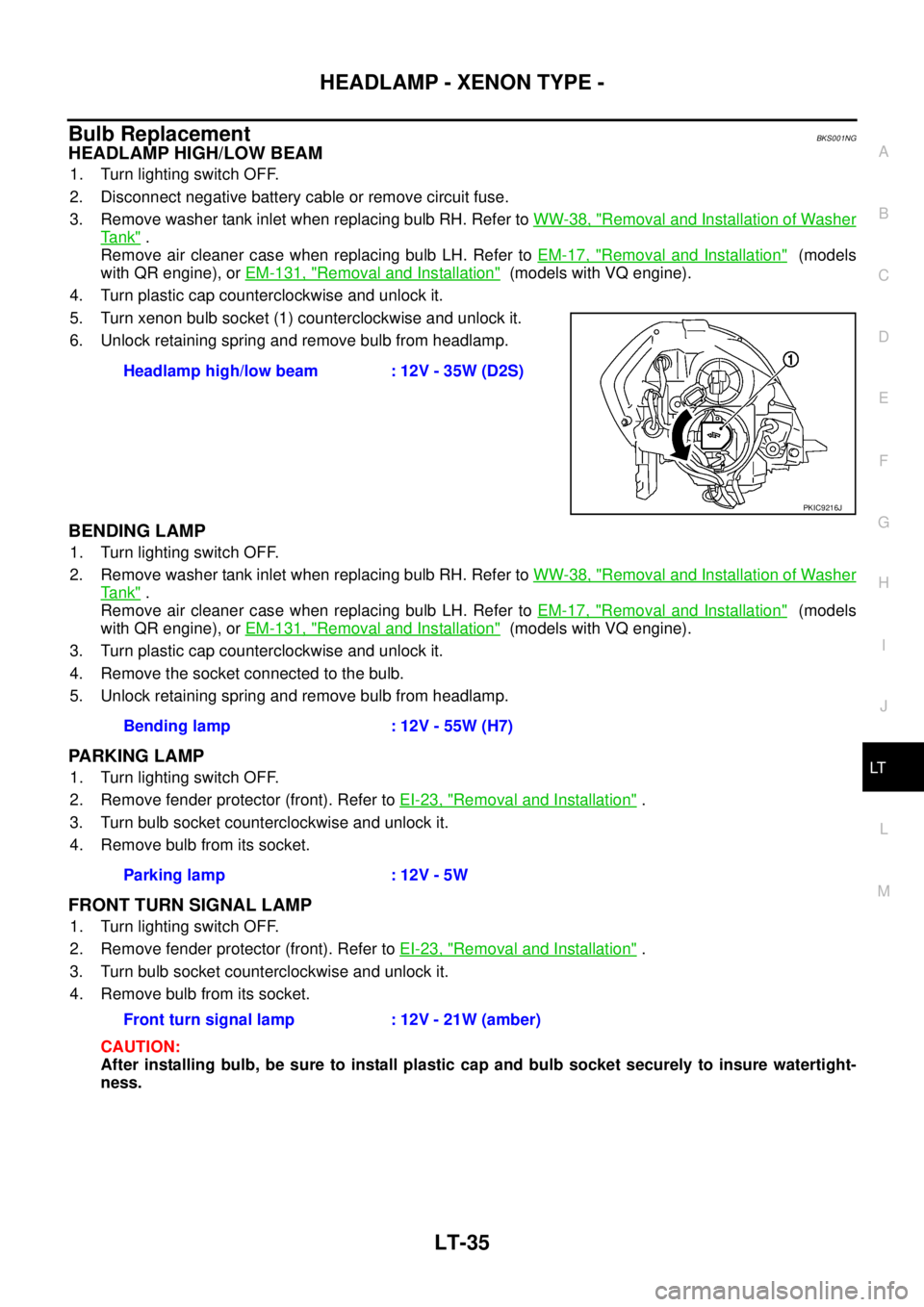
Bulb ReplacementBKS001NG
HEADLAMP HIGH/LOW BEAM
1. Turn lighting switch OFF.
2. Disconnect negative battery cable or remove circuit fuse.
3. Remove washer tank inlet when replacing bulb RH. Refer to WW-38, "
Removal and Installation of Washer
Ta n k" .
Remove air cleaner case when replacing bulb LH. Refer to EM-17, "
Removal and Installation" (models
with QR engine), or EM-131, "
Removal and Installation" (models with VQ engine).
4. Turn plastic cap counterclockwise and unlock it.
5. Turn xenon bulb socket (1) counterclockwise and unlock it.
6. Unlock retaining spring and remove bulb from headlamp.
BENDING LAMP
1. Turn lighting switch OFF.
2. Remove washer tank inlet when replacing bulb RH. Refer to WW-38, "
Removal and Installation of Washer
Ta n k" .
Remove air cleaner case when replacing bulb LH. Refer to EM-17, "
Removal and Installation" (models
with QR engine), or EM-131, "
Removal and Installation" (models with VQ engine).
3. Turn plastic cap counterclockwise and unlock it.
4. Remove the socket connected to the bulb.
5. Unlock retaining spring and remove bulb from headlamp.
PARKING LAMP
1. Turn lighting switch OFF.
2. Remove fender protector (front). Refer to EI-23, "
Removal and Installation" .
3. Turn bulb socket counterclockwise and unlock it.
4. Remove bulb from its socket.
FRONT TURN SIGNAL LAMP
1. Turn lighting switch OFF.
2. Remove fender protector (front). Refer to EI-23, "
Removal and Installation" .
3. Turn bulb socket counterclockwise and unlock it.
4. Remove bulb from its socket.
CAUTION:
After installing bulb, be sure to install plastic cap and bulb socket securely to insure watertight-
ness.Headlamp high/low beam : 12V - 35W (D2S)
PKIC9216J
Bending lamp : 12V - 55W (H7)
Parking lamp : 12V - 5W
Front turn signal lamp : 12V - 21W (amber)
Page 2750 of 3502
LT-62
HEADLAMP - HALOGEN TYPE -
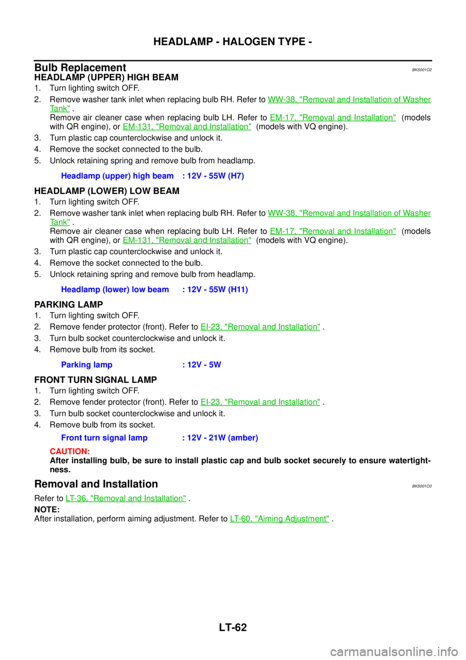
Bulb ReplacementBKS001O2
HEADLAMP (UPPER) HIGH BEAM
1. Turn lighting switch OFF.
2. Remove washer tank inlet when replacing bulb RH. Refer to WW-38, "
Removal and Installation of Washer
Ta n k" .
Remove air cleaner case when replacing bulb LH. Refer to EM-17, "
Removal and Installation" (models
with QR engine), or EM-131, "
Removal and Installation" (models with VQ engine).
3. Turn plastic cap counterclockwise and unlock it.
4. Remove the socket connected to the bulb.
5. Unlock retaining spring and remove bulb from headlamp.
HEADLAMP (LOWER) LOW BEAM
1. Turn lighting switch OFF.
2. Remove washer tank inlet when replacing bulb RH. Refer to WW-38, "
Removal and Installation of Washer
Ta n k" .
Remove air cleaner case when replacing bulb LH. Refer to EM-17, "
Removal and Installation" (models
with QR engine), or EM-131, "
Removal and Installation" (models with VQ engine).
3. Turn plastic cap counterclockwise and unlock it.
4. Remove the socket connected to the bulb.
5. Unlock retaining spring and remove bulb from headlamp.
PARKING LAMP
1. Turn lighting switch OFF.
2. Remove fender protector (front). Refer to EI-23, "
Removal and Installation" .
3. Turn bulb socket counterclockwise and unlock it.
4. Remove bulb from its socket.
FRONT TURN SIGNAL LAMP
1. Turn lighting switch OFF.
2. Remove fender protector (front). Refer to EI-23, "
Removal and Installation" .
3. Turn bulb socket counterclockwise and unlock it.
4. Remove bulb from its socket.
CAUTION:
After installing bulb, be sure to install plastic cap and bulb socket securely to ensure watertight-
ness.
Removal and InstallationBKS001O3
Refer to LT- 3 6 , "Removal and Installation" .
NOTE:
After installation, perform aiming adjustment. Refer to LT- 6 0 , "
Aiming Adjustment" . Headlamp (upper) high beam : 12V - 55W (H7)
Headlamp (lower) low beam : 12V - 55W (H11)
Parking lamp : 12V - 5W
Front turn signal lamp : 12V - 21W (amber)
Page 2949 of 3502
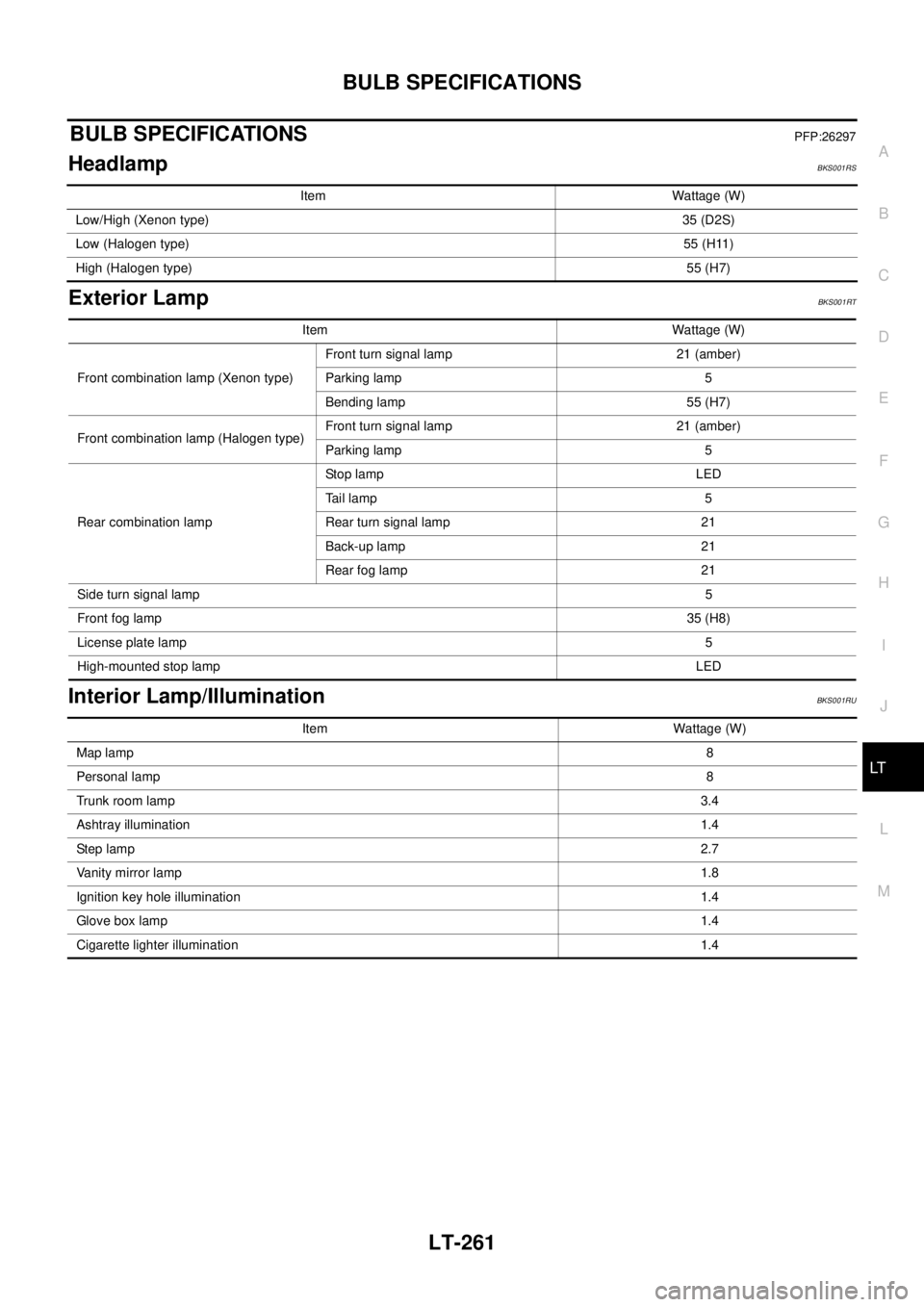
BULB SPECIFICATIONS
LT-261
C
D
E
F
G
H
I
J
L
MA
B
LT
BULB SPECIFICATIONSPFP:26297
HeadlampBKS001RS
Exterior LampBKS001RT
Interior Lamp/IlluminationBKS001RU
Item Wattage (W)
Low/High (Xenon type)35 (D2S)
Low (Halogen type)55 (H11)
High (Halogen type)55 (H7)
Item Wattage (W)
Front combination lamp (Xenon type)Front turn signal lamp 21 (amber)
Parking lamp 5
Bending lamp 55 (H7)
Front combination lamp (Halogen type)Front turn signal lamp 21 (amber)
Parking lamp 5
Rear combination lampStop lamp LED
Tail lamp 5
Rear turn signal lamp 21
Back-up lamp 21
Rear fog lamp 21
Side turn signal lamp5
Front fog lamp35 (H8)
License plate lamp5
High-mounted stop lampLED
Item Wattage (W)
Map lamp8
Personal lamp8
Trunk room lamp3.4
Ashtray illumination1.4
Step lamp2.7
Vanity mirror lamp1.8
Ignition key hole illumination1.4
Glove box lamp1.4
Cigarette lighter illumination1.4