Page 71 of 3502

TROUBLE DIAGNOSIS
AT-63
D
E
F
G
H
I
J
K
L
MA
B
AT
OthersMaximum speed
not attained.
Acceleration
poor.ON vehicle1. A/T fluid levelAT- 1 4
2. PNP switchAT- 1 6 1
3. 3rd position switchAT- 1 6 1
4. Accelerator pedal position sensor
EC-272*1, EC-652*2
5. Vehicle speed sensor·A/T (Revolution
sensor) and vehicle speed sensor·MTRAT- 8 0, AT- 8 6
6. Shift solenoid valve AAT- 9 0
7. Shift solenoid valve BAT- 9 5
8. Control valve assemblyAT- 2 2 5
OFF vehicle9. Reverse clutchAT- 2 9 6
10. High clutchAT- 3 0 1
11. Brake bandAT- 3 2 9
12. Low & reverse brakeAT- 3 1 5
13. Oil pumpAT- 2 7 5
14. Torque converterAT- 2 5 5
Transaxle noise
in “D”, “3”, “2”, “1”
and “R” positions.ON vehicle 1. A/T fluid levelAT- 1 4
OFF vehicle 2. Torque converterAT- 2 5 5
Engine brake
does not operate
in “1” position.ON vehicle1. PNP switchAT- 1 6 1
2. A/T positionAT- 2 1 5
3. Vehicle speed sensor·A/T (Revolution
sensor) and vehicle speed sensor·MTRAT- 8 0, AT- 8 6
4. Control valve assemblyAT- 2 2 5
5. Overrun clutch solenoid valveAT- 1 0 0
OFF vehicle6. Overrun clutchAT- 3 0 77. Low & reverse brakeAT- 3 1 5
Transaxle over-
heats.ON vehicle1. A/T fluid levelAT- 1 4
2. Engine idle speed
EC-45*1, EC-387*2
3. Accelerator pedal position sensor
EC-272*1, EC-652*2
4. Line pressure testAT- 4 6
5. Line pressure solenoid valveAT- 1 2 6
6. Control valve assemblyAT- 2 2 5
OFF vehicle7. Oil pumpAT- 2 7 5
8. Reverse clutchAT- 2 9 6
9. High clutchAT- 3 0 1
10. Brake bandAT- 3 2 9
11. Forward clutchAT- 3 0 7
12. Overrun clutchAT- 3 0 7
13. Low & reverse brakeAT- 3 1 5
14. Torque converterAT- 2 5 5
Items Symptom Condition Diagnostic item Reference page
Page 72 of 3502

AT-64
TROUBLE DIAGNOSIS
*1: QR engine
*2: VQ engine
TCM Terminals and Reference ValueBCS0010C
TCM CONNECTOR TERMINAL LAYOUT
TCM INSPECTION TABLE
Data are reference value and are measured between each terminal and ground.
OthersATF shoots out
during operation.
White smoke
emitted from
exhaust pipe dur-
ing operation.ON vehicle 1. A/T fluid levelAT- 1 4
OFF vehicle2. Reverse clutchAT-296
3. High clutchAT-301
4. Brake bandAT-329
5. Forward clutchAT-307
6. Overrun clutchAT-307
7. Low & reverse brakeAT-315
Offensive smell at
fluid charging
pipe.ON vehicle 1. A/T fluid levelAT- 1 4
OFF vehicle2. Torque converterAT-255
3. Oil pumpAT-275
4. Reverse clutchAT-296
5. High clutchAT-301
6. Brake bandAT-329
7. Forward clutchAT-307
8. Overrun clutchAT-307
9. Low & reverse brakeAT-315
Items Symptom Condition Diagnostic item Reference page
SCIA0495E
Terminal Wire color Item ConditionJudgement stan-
dard (Approx.)
1 G/RLine pressure sole-
noid valveWhen releasing accelerator pedal
after warming up engine.1.5 - 3.0 V
When depressing accelerator pedal
fully after warming up engine.0V
2W/BLine pressure sole-
noid valve (with drop-
ping resistor)When releasing accelerator pedal
after warming up engine.4 - 14 V
When depressing accelerator pedal
fully after warming up engine.0V
3 G/BTorque converter
clutch solenoid valveWhen A/T performs lock-up. 8 - 15 V
When A/T does not perform lock-up. 0 V
5 L CAN-H — —
6P CAN-L — —
Page 185 of 3502

TROUBLE DIAGNOSIS FOR SYMPTOMS
AT-177
D
E
F
G
H
I
J
K
L
MA
B
AT
4. DETECT MALFUNCTIONING ITEM
1. Disassemble A/T. Refer to AT- 2 5 5 , "
Disassembly" .
2. Check the following items:
–Forward clutch assembly. Refer to AT- 3 0 7 , "Forward and Overrun Clutches" .
–Overrun clutch assembly. Refer to AT- 3 0 7 , "Forward and Overrun Clutches" .
–Reverse clutch assembly. Refer to AT- 2 9 6 , "Reverse Clutch" .
OK or NG
OK >> GO TO 5.
NG >> Repair or replace damaged parts.
5. SYMPTOM CHECK
Check again. Refer to AT- 4 8 , "
Check at Idle" .
OK or NG
OK >>INSPECTION END
NG >> GO TO 6.
6. CHECK TCM
1. Check TCM input/output signals. Refer to AT- 6 4 , "
TCM Terminals and Reference Value" .
2. If NG, recheck TCM pin terminals for damage or loose connection with harness connector.
OK or NG
OK >>INSPECTION END
NG >> Repair or replace damaged parts.
Large Shock. “N” → “R” PositionBCS0014D
SYMPTOM:
Large shock when shifting from “N” to “R” position.
DIAGNOSTIC PROCEDURE
1. CHECK SELF-DIAGNOSTIC RESULTS (ECM)
Perform self-diagnosis. Refer to EC-82, "
SELF-DIAG RESULTS MODE" (QR engine) or EC-427, "SELF-
DIAG RESULTS MODE" (VQ engine).
Is any malfunction detected by self-diagnostic results?
YES >> Check the malfunctioning system. Refer to EC-82, "SELF-DIAG RESULTS MODE" (QR engine)
or EC-427, "
SELF-DIAG RESULTS MODE" (VQ engine).
NO >> GO TO 2.
2. CHECK SELF-DIAGNOSTIC RESULTS (TCM)
Perform self-diagnosis. Refer to AT- 6 9 , "
SELF-DIAGNOSTIC RESULT MODE" or AT- 7 6 , "Diagnostic Proce-
dure Without CONSULT-II" .
Is any malfunction detected by self-diagnostic results?
YES >> Check the malfunctioning systems. Refer to AT- 6 9 , "SELF-DIAGNOSTIC RESULT MODE" or AT-
77, "Judgement of Self-Diagnosis Code" .
NO >> GO TO 3.
Page 187 of 3502

TROUBLE DIAGNOSIS FOR SYMPTOMS
AT-179
D
E
F
G
H
I
J
K
L
MA
B
AT
Vehicle Does Not Creep Backward in “R” PositionBCS0014E
SYMPTOM:
Vehicle does not creep backward when selecting “R” position.
DIAGNOSTIC PROCEDURE
1. CHECK A/T FLUID LEVEL
Check A/T fluid level. Refer to AT- 1 4 , "
Checking A/T Fluid" .
OK or NG
OK >> GO TO 2.
NG >> Refill ATF.
2. CHECK LINE PRESSURE
Check line pressure at idle with selector lever in “R” position. Refer to AT- 4 6 , "
LINE PRESSURE TEST" .
OK or NG
OK >> GO TO 4.
NG >> GO TO 3.
3. DETECT MALFUNCTIONING ITEM
1. Remove control valve assembly. Refer to AT- 2 2 5 , "
Control Valve Assembly and Accumulators" .
2. Check the following items:
–Valves to control line pressure (Pressure regulator valve, pressure modifier valve, pilot valve and pilot fil-
ter)
–Line pressure solenoid valve
3. Disassemble A/T. Refer to AT- 2 5 5 , "
Disassembly" .
4. Check the following item:
–Oil pump assembly. Refer to AT- 2 7 5 , "Oil Pump" .
OK or NG
OK >> GO TO 4.
NG >> Repair or replace damaged parts.
4. CHECK STALL REVOLUTION
Check stall revolution with selector lever in “1” and “R” positions. Refer to AT- 4 3 , "
STALL TEST" .
OK or NG
OK >> GO TO 6.
OK in “1” position, NG in “R” position>> GO TO 5.
NG in both “1” and “R” positions>> GO TO 7.
5. DETECT MALFUNCTIONING ITEM
1. Disassemble A/T. Refer to AT- 2 5 5 , "
Disassembly" .
2. Check the following items:
–Low & reverse brake assembly. Refer to AT- 3 1 5 , "Low & Reverse Brake" .
–Reverse clutch assembly. Refer to AT- 2 9 6 , "Reverse Clutch" .
OK or NG
OK >> GO TO 6.
NG >> Repair or replace damaged parts.
Page 188 of 3502

AT-180
TROUBLE DIAGNOSIS FOR SYMPTOMS
6. CHECK A/T FLUID CONDITION
1. Remove oil pan. Refer to AT- 2 4 6 , "
Components" .
2. Check A/T fluid condition. Refer to AT- 4 3 , "
A/T Fluid Condition Check" .
OK or NG
OK >> GO TO 8.
NG >> GO TO 7.
7. DETECT MALFUNCTIONING ITEM
1. Disassemble A/T. Refer to AT- 2 5 5 , "
Disassembly" .
2. Check the following items:
–Reverse clutch assembly. Refer to AT- 2 9 6 , "Reverse Clutch" .
–High clutch assembly. Refer to AT- 3 0 1 , "High Clutch" .
–Low & reverse brake assembly. Refer to AT- 3 1 5 , "Low & Reverse Brake" .
–Forward clutch assembly. Refer to AT- 3 0 7 , "Forward and Overrun Clutches" .
–Overrun clutch assembly. Refer to AT- 3 0 7 , "Forward and Overrun Clutches" .
OK or NG
OK >> GO TO 8.
NG >> Repair or replace damaged parts.
8. SYMPTOM CHECK
Check again. Refer to AT- 4 8 , "
Check at Idle" .
OK or NG
OK >>INSPECTION END
NG >> GO TO 9.
9. CHECK TCM
1. Check TCM input/output signals. Refer to AT- 6 4 , "
TCM Terminals and Reference Value" .
2. If NG, recheck TCM pin terminals for damage or loose connection with harness connector.
OK or NG
OK >>INSPECTION END
NG >> Repair or replace damaged parts.
Page 215 of 3502
TROUBLE DIAGNOSIS FOR SYMPTOMS
AT-207
D
E
F
G
H
I
J
K
L
MA
B
AT
6. DETECT MALFUNCTIONING ITEM
1. Remove control valve assembly. Refer to AT- 2 2 5 , "
Control Valve Assembly and Accumulators" .
2. Check the following items:
–Shift valve B
–Overrun clutch solenoid valve
3. Disassemble A/T. Refer to AT- 2 5 5 , "
Disassembly" .
4. Check the following items:
–Overrun clutch assembly. Refer to AT- 3 0 7 , "Forward and Overrun Clutches" .
–Low & reverse brake assembly. Refer to AT- 3 1 5 , "Low & Reverse Brake" .
OK or NG
OK >> GO TO 7.
NG >> Repair or replace damaged parts.
7. SYMPTOM CHECK
Check again. Refer to AT- 5 2 , "
Cruise Test — Part 3" .
OK or NG
OK >>INSPECTION END
NG >> GO TO 8.
8. CHECK TCM
1. Check TCM input/output signals. Refer to AT- 6 4 , "
TCM Terminals and Reference Value" .
2. If NG, recheck TCM pin terminals for damage or loose connection with harness connector.
OK or NG
OK >> INSPECTION END
NG >> Repair or replace damaged parts.
Page 218 of 3502

AT-210
TROUBLE DIAGNOSIS FOR SYMPTOMS
6. DETECT MALFUNCTIONING ITEM
1. Remove control valve assembly. Refer to AT- 2 2 5 , "
Control Valve Assembly and Accumulators" .
2. Check the following items:
–Shift valve A
–Overrun clutch solenoid valve
3. Disassemble A/T. Refer to AT- 2 5 5 , "
Disassembly" .
4. Check the following items:
–Overrun clutch assembly. Refer to AT- 3 0 7 , "Forward and Overrun Clutches" .
–Low & reverse brake assembly. Refer to AT- 3 1 5 , "Low & Reverse Brake" .
OK or NG
OK >> GO TO 7.
NG >> Repair or replace damaged parts.
7. SYMPTOM CHECK
Check again. Refer to AT- 5 2 , "
Cruise Test — Part 3" .
OK or NG
OK >>INSPECTION END
NG >> GO TO 8.
8. CHECK TCM
1. Check TCM input/output signals. Refer to AT- 6 4 , "
TCM Terminals and Reference Value" .
2. If NG, recheck TCM pin terminals for damage or loose connection with harness connector.
OK or NG
OK >> INSPECTION END
NG >> Repair or replace damaged parts.
TCM Self-diagnosis Does Not ActivateBCS0014V
SYMPTOM:
A/T CHECK indicator lamp does not come on in TCM self-diagnostic procedure even if the lamp circuit
is good.
DESCRIPTION
�PNP switch
PNP switch includes a transmission range switch. The transmission range switch detects the selector
lever position and sends a signal to the TCM.
�3rd position switch
3rd position switch detects the 3rd position and sends a signal via CAN communication to the TCM.
�Closed throttle position signal and wide-open throttle position signal.
ECM judges throttle opening based on a signal from accelerator pedal position (APP) sensor, and sends
the signal via CAN communication to TCM.
�Stop lamp switch
Stop lamp switch detects the switch position (ON or OFF) and sends a signal via CAN communication to
the TCM.
DIAGNOSTIC PROCEDURE
NOTE:
The diagnostic procedure includes inspection for the park/neutral position (PNP) stitch, 3rd position switch,
stop lamp switch, closed throttle position signal and wide open throttle position signal circuit. Refer to AT- 1 6 1 ,
"PNP, 3RD POSITION SWITCH AND CLOSED THROTTLE, WIDE OPEN THROTTLE POSITION SIGNAL"
and AT- 1 6 7 , "BRAKE SIGNAL CIRCUIT" .
Page 220 of 3502
AT-212
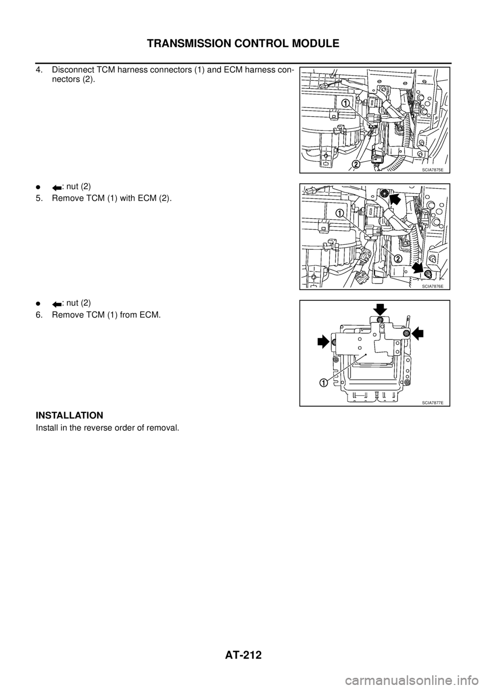
TRANSMISSION CONTROL MODULE
4. Disconnect TCM harness connectors (1) and ECM harness con-
nectors (2).
�: nut (2)
5. Remove TCM (1) with ECM (2).
�: nut (2)
6. Remove TCM (1) from ECM.
INSTALLATION
Install in the reverse order of removal.
SCIA7875E
SCIA7876E
SCIA7877E