Page 257 of 3502

OVERHAUL
AT-249
D
E
F
G
H
I
J
K
L
MA
B
AT
10. D-ring 11. Reverse clutch drum 12. Thrust washer
13. Reverse clutch assembly 14. Drive plate 15. Needle bearing
16. Bearing race 17. Front sun gear 18. Needle bearing
19. High clutch hub 20. Needle bearing 21. Snap ring
22. Retaining plate 23. Driven plate 24. Snap ring
25. Spring retainer assembly 26. D-ring 27. D-ring
28. High clutch piston 29. Input shaft assembly (high clutch
drum)30. Seal ring
31. Needle bearing 32. Bearing race 33. High clutch assembly
34. Drive plate 35. Needle bearing 36. Overrun clutch hub
37. Thrust washer 38. Bearing race 39. Forward one-way clutch
40. Bearing race 41. Forward clutch hub 42. Thrust washer
43. Rear internal gear 44. Needle bearing 45. Rear planetary carrier
46. Rear sun gear 47. Front planetary carrier 48. Spring retainer
49. D-ring 50. D-ring 51. Low & reverse brake piston
52. Retainer 53. Snap ring 54. Low one-way clutch
55. Snap ring 56. Needle bearing 57. Needle bearing
58. Forward clutch drum 59. Forward clutch piston 60. Seal lip
61. D-ring 62. Spring retainer assembly 63. Snap ring
64. Dish plate 65. Driven plate 66. Retaining plate
67. Snap ring 68. Dish plate 69. Retaining plate
70. Driven plate 71. Retaining plate 72. Retaining plate
73. Snap ring 74. Forward clutch assembly and over-
run clutch assembly75. Drive plate
76. Drive plate 77. Overrun clutch piston 78. D-ring
79. Seal lip 80. Retaining plate 81. Driven plate
82. Low & reverse brake assembly 83. Snap ring 84. Retaining plate
85. Dish plate 86. Drive plate
Refer to GI section to make sure icons (symbol marks) in the figure. Refer to GI-10, "
Components" .
Page 259 of 3502
12. Bracket
13. Anchor end pin 14. Lock nut 15. Transaxle case
16. Brake band 17. B")
OVERHAUL
AT-251
D
E
F
G
H
I
J
K
L
MA
B
AT
10. O-ring 11. Turbine revolution sensor (power
train revolution sensor)12. Bracket
13. Anchor end pin 14. Lock nut 15. Transaxle case
16. Brake band 17. Bearing retainer 18. Seal ring
19. Radial needle bearing 20. Snap ring 21. Reduction pinion gear
22. Reduction pinion gear bearing inner
race23. Reduction pinion gear bearing outer
race24. Strut
25. O-ring 26. O-ring 27. Servo release accumulator piston
28. O-ring 29. Return spring 30. Control valve assembly
31. Oil pan gasket 32. Drain plug gasket 33. Drain plug
34. Magnet 35. Oil pan 36. Oil pan fitting bolt
37. Low & reverse brake tube 38. Oil sleeve 39. O-ring
40. Snap ring 41. O-ring 42. N-D accumulator piston
43. Return spring 44. Lip seal 45. Parking rod
46. Retaining pin 47. Manual shaft oil seal 48. Detent spring
49. Manual shaft 50. Retaining pin 51. Manual plate
52. Parking rod plate 53. O/D servo piston 54. O/D servo piston retainer
55. O/D servo piston retainer fitting bolt 56. O-ring 57. D-ring
58. Servo piston retainer 59. O-ring 60. E-ring
61. Spring retainer 62. O/D servo return spring 63. D-ring
64. Band servo piston 65. Band servo thrust washer 66. Band servo piston stem
67. 2nd servo return spring 68. Parking pawl 69. Parking shaft
70. Return spring 71. Paring pawl spacer 72. PNP switch
73. Idler gear bearing 74. Idler gear 75. Idler gear lock nut
76. Reduction pinion gear adjusting
shim77. Output shaft adjusting shim 78. Side cover
Refer to GI section to make sure icons (symbol marks) in the figure. Refer to GI-10, "
Components" .
However, refer to the following symbol for others.
: Apply locking sealant (Loctite #518).
Page 267 of 3502
DISASSEMBLY
AT-259
D
E
F
G
H
I
J
K
L
MA
B
AT
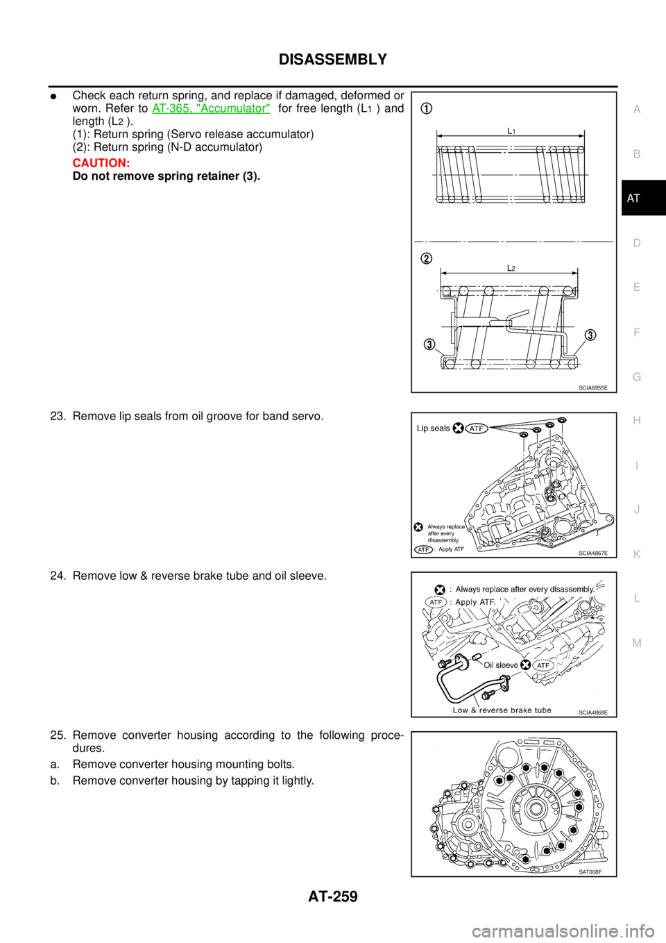
�Check each return spring, and replace if damaged, deformed or
worn. Refer to AT- 3 6 5 , "
Accumulator" for free length (L1 ) and
length (L
2 ).
(1): Return spring (Servo release accumulator)
(2): Return spring (N-D accumulator)
CAUTION:
Do not remove spring retainer (3).
23. Remove lip seals from oil groove for band servo.
24. Remove low & reverse brake tube and oil sleeve.
25. Remove converter housing according to the following proce-
dures.
a. Remove converter housing mounting bolts.
b. Remove converter housing by tapping it lightly.
SCIA6955E
SCIA4867E
SCIA4868E
SAT008F
Page 271 of 3502
DISASSEMBLY
AT-263
D
E
F
G
H
I
J
K
L
MA
B
AT
c. Check brake band facing for damage, cracks, wear or burns.
�Replace brake band if necessary.
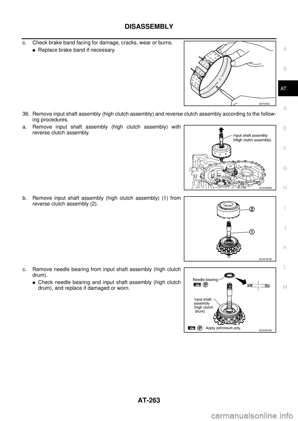
36. Remove input shaft assembly (high clutch assembly) and reverse clutch assembly according to the follow-
ing procedures.
a. Remove input shaft assembly (high clutch assembly) with
reverse clutch assembly.
b. Remove input shaft assembly (high clutch assembly) (1) from
reverse clutch assembly (2).
c. Remove needle bearing from input shaft assembly (high clutch
drum).
�Check needle bearing and input shaft assembly (high clutch
drum), and replace if damaged or worn.
SAT040D
SCIA4009E
SCIA7818E
SCIA4872E
Page 272 of 3502
AT-264
DISASSEMBLY
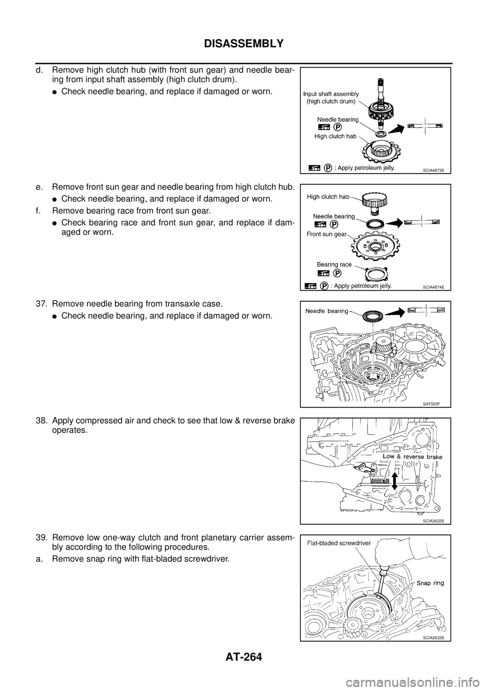
d. Remove high clutch hub (with front sun gear) and needle bear-
ing from input shaft assembly (high clutch drum).
�Check needle bearing, and replace if damaged or worn.
e. Remove front sun gear and needle bearing from high clutch hub.
�Check needle bearing, and replace if damaged or worn.
f. Remove bearing race from front sun gear.
�Check bearing race and front sun gear, and replace if dam-
aged or worn.
37. Remove needle bearing from transaxle case.
�Check needle bearing, and replace if damaged or worn.
38. Apply compressed air and check to see that low & reverse brake
operates.
39. Remove low one-way clutch and front planetary carrier assem-
bly according to the following procedures.
a. Remove snap ring with flat-bladed screwdriver.
SCIA4873E
SCIA4874E
SAT020F
SCIA3632E
SCIA3633E
Page 273 of 3502
DISASSEMBLY
AT-265
D
E
F
G
H
I
J
K
L
MA
B
AT
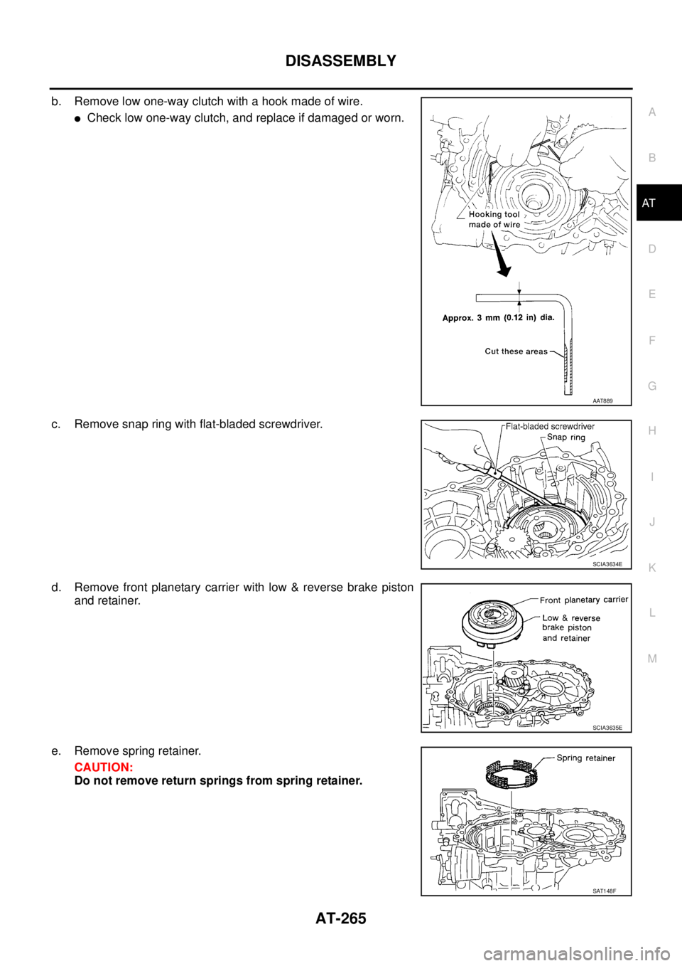
b. Remove low one-way clutch with a hook made of wire.
�Check low one-way clutch, and replace if damaged or worn.
c. Remove snap ring with flat-bladed screwdriver.
d. Remove front planetary carrier with low & reverse brake piston
and retainer.
e. Remove spring retainer.
CAUTION:
Do not remove return springs from spring retainer.
AAT889
SCIA3634E
SCIA3635E
SAT148F
Page 274 of 3502
AT-266
DISASSEMBLY
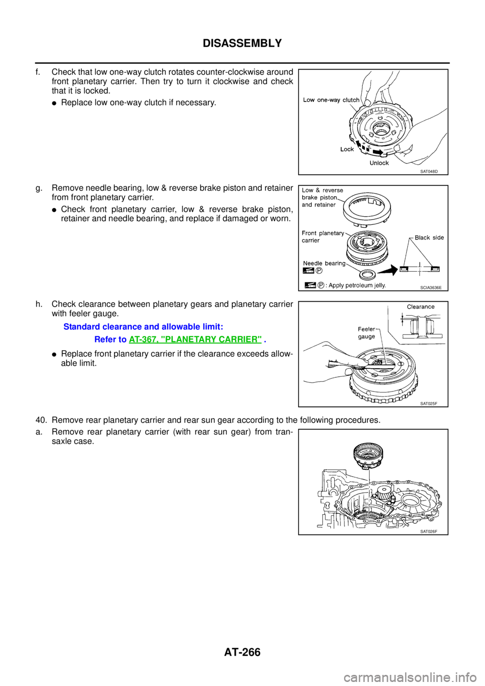
f. Check that low one-way clutch rotates counter-clockwise around
front planetary carrier. Then try to turn it clockwise and check
that it is locked.
�Replace low one-way clutch if necessary.
g. Remove needle bearing, low & reverse brake piston and retainer
from front planetary carrier.
�Check front planetary carrier, low & reverse brake piston,
retainer and needle bearing, and replace if damaged or worn.
h. Check clearance between planetary gears and planetary carrier
with feeler gauge.
�Replace front planetary carrier if the clearance exceeds allow-
able limit.
40. Remove rear planetary carrier and rear sun gear according to the following procedures.
a. Remove rear planetary carrier (with rear sun gear) from tran-
saxle case.
SAT048D
SCIA3636E
Standard clearance and allowable limit:
Refer to AT- 3 6 7 , "
PLANETARY CARRIER" .
SAT025F
SAT026F
Page 304 of 3502
AT-296
REPAIR FOR COMPONENT PARTS
Reverse ClutchBCS001OO
COMPONENTS
DISASSEMBLY
1. Check operation of reverse clutch
a. Install seal ring onto drum support of oil pump cover and install
reverse clutch assembly. Apply compressed air to oil hole.
b. Check to see that retaining plate moves to snap ring.
c. If retaining plate does not contact snap ring:
�D-ring might be damaged.
�Seal lip might be damaged.
�Fluid might be leaking past piston check ball.
2. Remove snap ring with flat-bladed screwdriver.
3. Remove drive plates, driven plates, retaining plate and dish
plates.
1. Reverse clutch drum 2. D-ring 3. Seal lip
4. Reverse clutch piston 5. Return spring 6. Spring retainer
7. Snap ring 8. Dish plate 9. Driven plate
10. Retaining plate 11. Snap ring 12. Drive plate
SCIA3889E
SCIA3316E
SCIA4886E